EasyManua.ls Logo

Honeywell ML7421A1032 User Manual

Honeywell ML7421A1032
8 pages
To Next Page IconTo Next Page
Page #1 background imageLoading...
Page #1 background image
PRODUCT DATA
® U.S. Registered Trademark
Copyright © 1999 Honeywell Inc. • All Rights Reserved
ML7421A,B
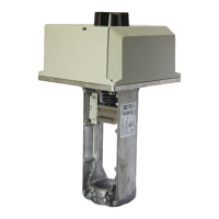
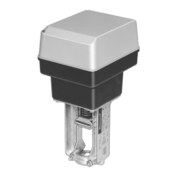
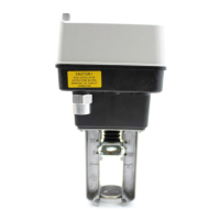
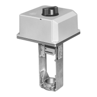
Electric Linear Valve Actuator
GENERAL
The ML7421A,B Electric Linear Valve Actuators for
modulating controlare equipped with a stepper motor for
exact positioning. The direction of movement is reversible by
means of an internal selector plug. These actuators operate
standard Honeywell valves in heating, ventilating, and air
conditioning (HVAC) applications.
63-2517-2
FEATURES
Quick and easy installation.
No separate linkage required.
3/4 in. (20 mm) stroke on ML7421A;
1-1/2 in. (38 mm) stroke on ML7421B.
No adjustments required.
Accurate valve positioning.
Selectable 0(2) to 10 Vdc/0(4) to 20 mA input signal.
Position feedback.
Force-limiting end switches.
Manual operator.
Direct or reverse acting.
Synchronous motor.
Corrosion resistant design.
Maintenance free.
Conduit connector knockout.
Contents
General ............................................................................ 1
Features .......................................................................... 1
Specifications .................................................................. 2
Installation ....................................................................... 3
Operation ......................................................................... 5
Checkout ......................................................................... 6
Ordering Information ....................................................... 7
Question and Answer IconNeed help?

Do you have a question about the Honeywell ML7421A1032 and is the answer not in the manual?

Honeywell ML7421A1032 Specifications

General IconGeneral
Voltage24 VAC
DisplayNo
Number of TurnsNot Applicable
Control SignalFloating, 4..20 mA, 0..10 Vdc
Operating Temperature-20 to 50 degrees Celsius

Summary

Installation

Location

Specifies the ideal placement for actuator installation and servicing.

Mounting

Details how to attach the actuator to the valve collar securely.

Operation

General Operation

Explains the synchronous motor drive and force sensor function.

Manual Operation

Guides users on how to operate the valve manually without power.

Signal Input and Failure

Signal Input

Details the analog input signal range and selector plug settings.

Signal Input Failure

Describes actuator behavior when the control signal fails.

Checkout

Direct Checkout

Steps to check actuator function without a controller.

Controller Checkout

Procedures for testing actuator response via a control system.

Output Signal Feedback and Direction

Output Signal Feedback

Explains the analog output signal for stem position indication.

Direction of Action

Describes how to change the actuator's stem extension/retraction direction.

Related product manuals