MO953
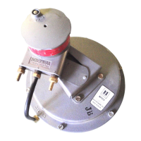
CONVERSION
JO CONVFRT A4
DFVICF-
8
IN. (203 MM)
RELAY ASSY 313695J
FEEDBACK SPRING
3 13696-00063
CUP 315178-00062
DIAPHRAGM 311750 OR
314153
72
-SCREW
Q-WASHER
@
-
PLATE
TO CONVFRT A8
DWICF-
13 IN. (330 MM)
RELAY ASSY
313695J
FEEDBACK SPRING
313814-00605
CUP 315178-00062
DIAPHRAGM 312505
CUP 315020-00124
CUP
31174O-OO602
-DIAPHRAGM
Fig. 6. MO953 Conversion.
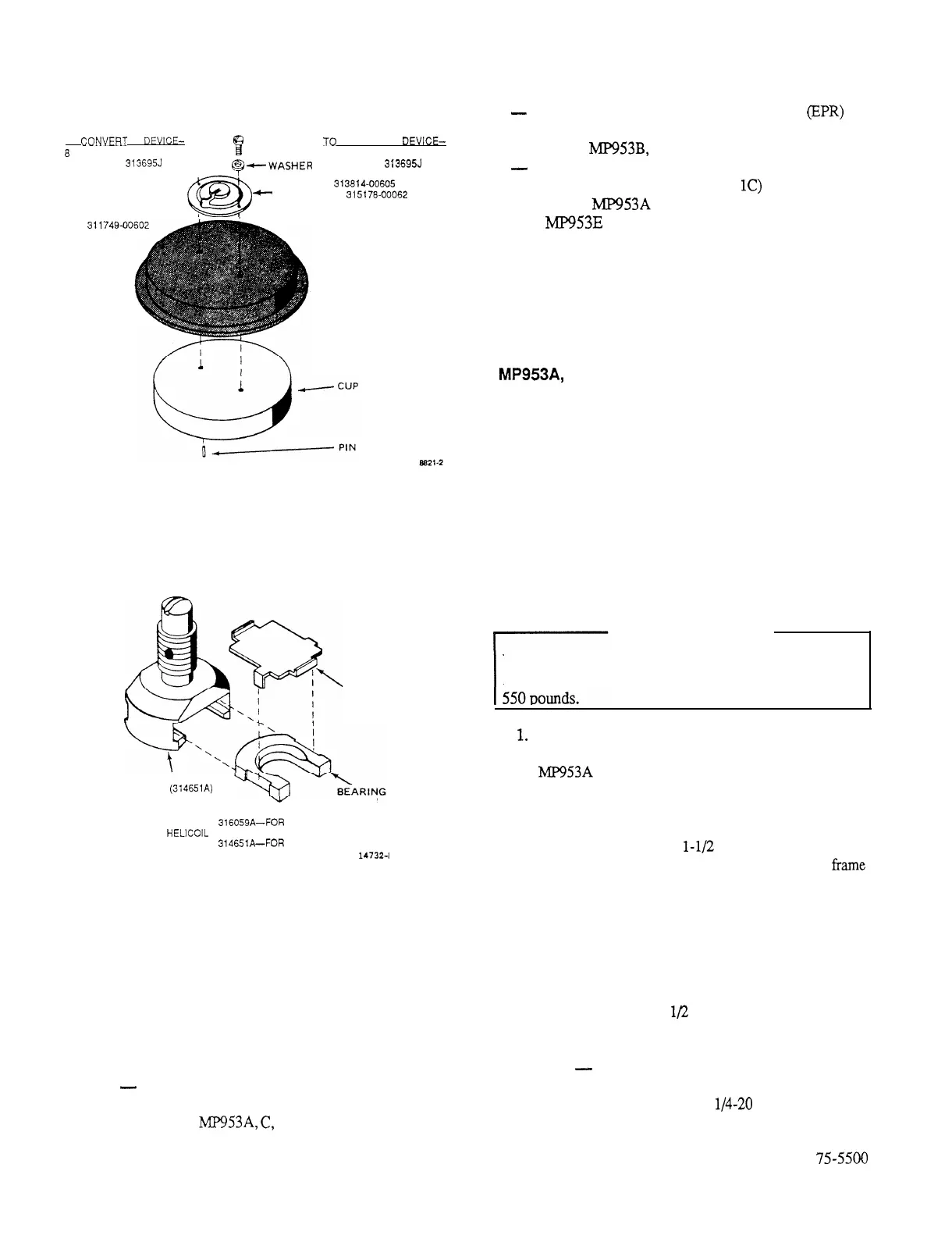
YOKE ASSEMBLY
SPRING
314652
YOKE
314651 (314651A)
316059 (316059A)
314653
ASSEMBLY
316059A-FOR
SUPPORT WITH
HELICOIL INSERT
ASSEMBLY
314651A-FOR
SUPPORT WITH
NYLON INSERT
14732-l
Fig. 7. Yoke Assembly.
REPLACE MAIN DIAPHRAGM
GENERAL
Before replacing the diaphragm, determine the type and
material of the existing diaphragm according to its color:
-
Black: Neoprene
Maximum temperature 160F (71C)
Used on
MP953A,
6,
and E
-
Black with white spot: Ethylene Propylene
(EPR)
Maximum temperature 250F (121C)
Used on
MP953B,
D and F
-
White: Silicone
Maximum temperature 250F (12
1C)
Used on
MP953A
and C and may be installed on
MP953E
Flat diaphragms and beaded-roll diaphragms are not
interchangeable. Neoprene and EPR diaphragms are
interchangeable but must meet maximum temperature
requirements.
MP953A, C, E DIRECT-ACTING ACTUATORS
Direct-acting Actuators are subject to extremely high
internal spring loads. Therefore, Actuator covers must be
removed very carefully before the the main diaphragm can
be replaced.
When using the following procedures, see Figures 8 and
10 for exploded diagrams and Tables 6 and 8 for parts.
REMOVE ACTUATOR COVER
A
WARNING
A
Use extreme caution when disassembling Actuators.
Actuator assemblies are under spring load which can reach
1.
2.
3.
4.
5.
6.
Disconnect all air lines, including any connected to
Gradutrol Relay or positive positioner, if present.
MP953A
and E only: Remove Relay/positioner from
Actuator cover by turning counterclockwise.
Remove exposed feedback spring.
See WARNING in this section. Loosen cover
setscrews sequentially
l-1/2
turns each.
Check whether cover can be squeezed back to
frame
by hand. If so, continue sequentially loosening screws
until cover is free. Remove cover, diaphragm, and go
to REPLACE DIAPHRAGM.
If cover cannot be squeezed back to frame, use the
following guides according to Actuator size.
NOTES:
a. Bolts should be threaded to within
approximately
l/2
in. of their heads.
b.
In each case, turn the long bolt in until its head
contacts the cover flange.
-
8-m Actuator: Remove two cover screws
that are directly opposite each other. Replace
cover screws with
l/4-20
x 3 in. bolts.
75-5500
 Loading...