OmniClass 2.0
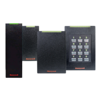
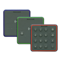
OM15/16/17/18, OM30/31/32/33, OM40/41/42/43, OM55/56/57/58
R10E/RP10E/R10MA/RP10MA, R15E/RP15E/R15MA/RP15MA, R40E/RP40E/R40MA/RP40MA, RK40E/RPK40E/RK40MA/RPK40MA
PLT-01558, Rev A.1INSTALLATION GUIDE Page 2
1 Mounting
Junction box not
included
Gasket optional
2 Wiring
P1
P2
18 in
(0.46 m)
BEEP
GRN
GND
+VDC
DRAIN
RED
HOLD
GPI01
GPI02
OC/TMPR
DATA1/CLK
DATA0/DATA
GPI03
GPI04
BEEP
GRN
GND
+VDC
DRAIN
RED
HOLD
GPI01
GPI02
OC/TMPR
DATA1/CLK
DATA0/DATA
GPI03
GPI04
BEEP (YEL)
GRN (ORG)
GND (BLK)
+VDC (RED)
DRAIN (BARE)
RED (BRN)
HOLD (BLU)
GPIO1 (RED/GRN)
GPIO2 (TAN)
OC/TMPR (VIO)
DATA1/CLK(WHT)
DATA0/DATA (GRN)
GPIO3 (PINK)
GPIO4 (GRAY)
PIGTAIL*** TERMINAL DESCRIPTION
Yellow P1-1 Beeper Input
Orange P1-2 LED Input (GRN)
Black P1-3 Ground (RTN)
Red P1-4 +VDC
Drain P1-5 Unused
Brown P1-6 LED Input (RED)
Blue P1-7 Hold Input
Red/Green P2-7 GPI01/OSDP (RS485-FDX/HDX-A)
Tan P2-6 GPI02/OSDP (RS485-FDX-HDX-B)
Violet P2-5 *Open Collector Output/Tamper
White P2-4 **Wiegand Data 1 / Clock
Green P2-3 **Wiegand Data 0 / Data
Pink P2-2 GPI03 (RS485-FDX-Z)
Gray P2-1 GPI04 (RS485-FDX-Y)
* Tamper Output. When activated, output syncs to ground (default).
** Dependent upon reader conguration. See HTOG Wiegand and Clock-and-Data congurations for more
information.
*** For 5 meter pigtail readers, PN: 9xxxxxLEKxxxxx follow the wiring diagram on the reader.
3 Install Reader to Backplate
4 Power & Testing
Turn on power Test card
Note: Previous OmniClass readers had reversed RS-485 wiring (P2-7 & P2-6 - A
& B). When upgrading to an OmniClass SE reader, ensure proper connections as
defined below.
Note: It’s possible to reuse existing Wiegand wiring for OSDP, however, using simple
stranded cable typical of Wiegand access control readers is usually not meeting the
RS485 twisted pair recommendations.
Note: For OSDP cable lengths greater than 200ft. (61M) or EMF interference, install
120Ω +/- 2Ω resistor across RS-485 termination ends.
Note: Wiring the reader incorrectly may permanently damage the reader.
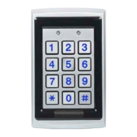
Note: With a keypad reader, operating as 26 bit emulation; upon power up you have
5 seconds to enter the facility code followed by #. If unsuccessful, the reader LED
displays solid Red. Power-cycle the reader and retry entering the facility code.
The facility code needs to be manually entered as 3 digits (i.e. if facility code is 10
enter 0-1-0-#). Note: OmniClass 2.0 readers only use facility codes between 1-255,
and there is no default facility code. Once the facility code has been entered, the LED
will display Violet and then to a final Red. Then power-cycle the reader. Note: When
using a keypad, if there are 2 short beeps after entering your PIN, the reader does
not have a facility code configured yet. In this event, an Admin will need to be power-
cycle the reader and enter the facility code before the reader will accept your PIN.
Optional Features
Open Collector Output - Controls an external device (5 VDC) operating in Host Mode only. Sink – 40mA / Source – 1mA.
Configuration Cards – With the use of configuration cards, the reader can be modified to meet the specific requirements of an installation. Configuration options include; audio
visual, CSN outputs and keypad outputs (keypad models only). Contact HID Technical Support for all reader configuration options.
Hold Input – when asserted, this line either buffers a card or disables a card read until released, as configured.
ATTENTION
Observe precautions for handling
ELECTROSTATIC SENSITIVE DEVICES
 Loading...