ER200 PERFECT WINDOW™ FRESH AIR VENTILATION SYSTEM
68-0131—2
10
쐊 When the supply air from the Fresh Air Ventilation
System is connected to the furnace return:
• Balance with the furnace blower
on
if the furnace
fan normally runs continuously.
• Balance with the furnace blower
off
if the furnace
fan runs only when the heating or cooling is on.
쐎 Tu rn on the Fresh Air Ventilation System. Wait 60 seconds
for airflows to stabilize. Record reading in the exhaust
air stream.
NOTE: If using a magnehelic gauge, tap lightly before
recording the reading.
쐅 Move the grid to the supply air stream and repeat steps
3 through 9.
쐈 To correct imbalance:
• Airflow is greater in supply air section of Fresh Air
Ventilation System—install a damper on the
downwind side of the ventilator (warm side) and
adjust until the airflow is within
+10 percent of the
exhaust airflow. See Fig. 10.
— When radon control is a concern, balance
the supply airflow to provide 10 to15 cfm (5 to
8 L/s) more airflow than the exhaust.
•
Airflow is greater in exhaust section of Fresh Air
Ventilation System
—install a damper on the
downwind side of the exhaust blower (cold side)
and adjust until the airflows are within +10 percent.
See Fig. 10.
— When radon control is a concern, balance so
that exhaust is 10 to 15 cfm (5 to 8 L/s) less
than supply airflow.
After the damper is adjusted and set, cover the damper with
insulated ducting and tape.
쐉 Mark the damper position on the duct for future
reference.
씈 Place a sticker on the unit and record airflows
measured while balancing, name of installer and date
for future reference.
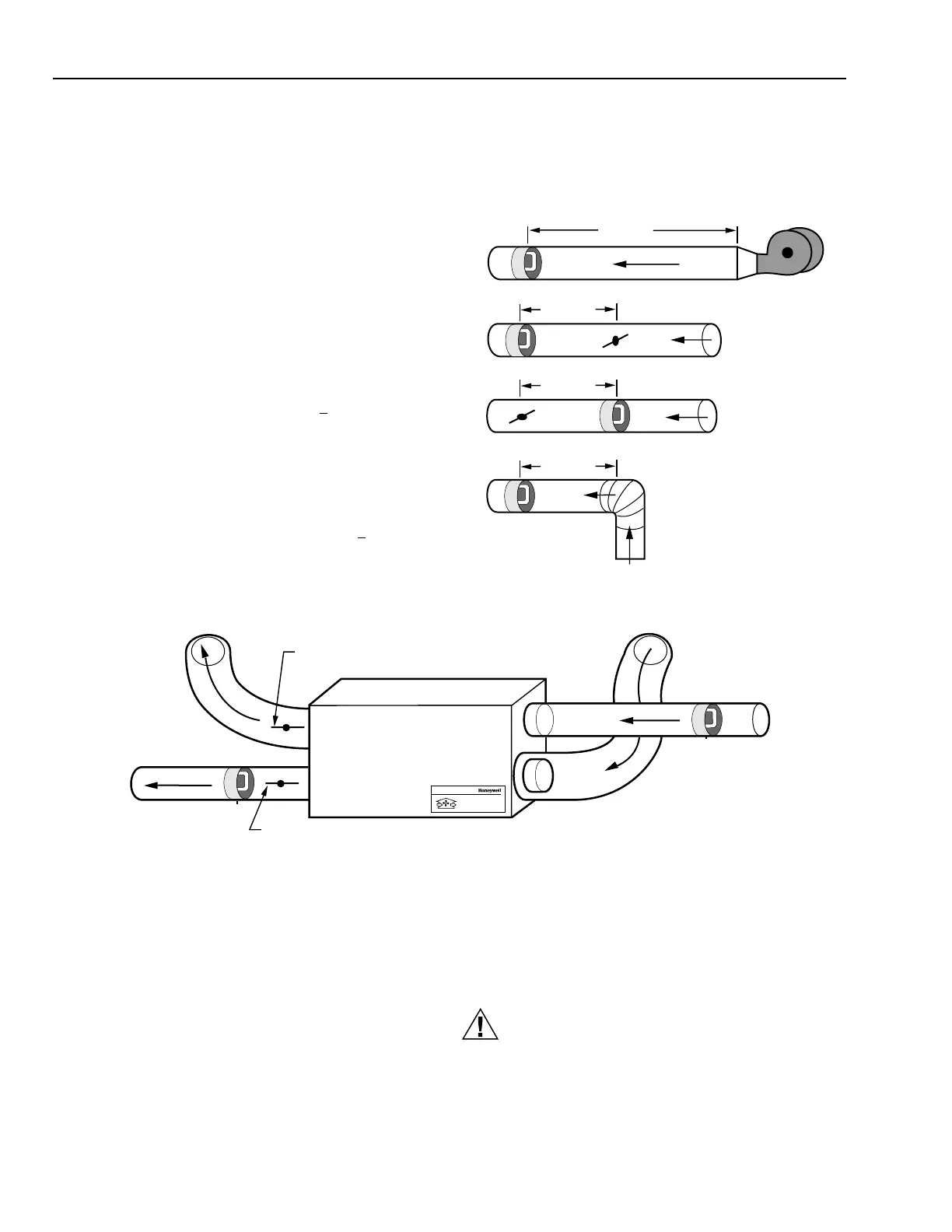
Fig. 9. Location of airflow grid in in. (mm).
30 IN (750)
12 IN (300)
12 IN (300)
12 IN (300)
M3102
STALE
AIR FROM
HOUSE
AIRFLOW GRID
INSTALL DAMPER DOWNWIND OF EXHAUST BLOWER IF AIRFLOW IS
GREATEST IN EXHAUST AIR. ADJUST TO EQUAL SUPPLY AIRFLOW.
INSTALL DAMPER DOWNWIND OF SUPPLY BLOWER IF AIRFLOW IS
GREATEST IN SUPPLY AIR. ADJUST TO EQUAL EXHAUST AIRFLOW.
FRESH AIR TO HOUSE
AIRFLOW GRID
M3109D
STALE AIR
EXHAUST
FRESH AIR
INTAKE
Fresh Air Ventilation System
Système de ventilation à air frais
Fig. 10. ER200 balancing airflow.
STARTUP AND CHECKOUT
After the installation and wiring are complete, make a final
check that all components are working.
쐃 Open the cabinet door.
쐇 Turn the master switch on the side of the cabinet to the
ON position.
쐋 Turn on fresh air control to verify airflow and wheel
rotation. Operate the control from MAX to MIN to verify
decrease in airflow.
쐏 Activate any line voltage override switch to verify
function. Master power switch must be on.
쐄 For the model equipped with preheat frost control,
check out operation of the frost control system by
momentarily depressing the press-to-test button located
on the top blower plate using a pen or small
screwdriver. The neon lamp adjacent to the test button
lights to indicate preheater operation.
CAUTION
Press button momentarily to avoid overheating unit.
Do not hold down button for more than two seconds.
Fresh air filter must be in place. Do not touch heater
element.
 Loading...