ER200 PERFECT WINDOW™ FRESH AIR VENTILATION SYSTEM
68-0131—2
6
Suspended Mounting
쐃 Attach two mounting straps to the bottom of the Fresh
Air Ventilation System cabinet. Use four of the no. 10-24
x 1/2 in. round head machine screws and four no. 10
internal tooth washers supplied in the hardware
package.
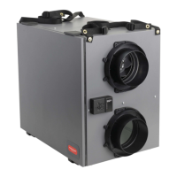
쐇 Attach a pair of hanging brackets to a joist. See Fig. 4.
Space the brackets 25-1/4 in. apart on centers. Use two
1-1/2 in. lag screws to secure each bracket.
쐋 Locate and attach the remaining pair of brackets on a
joist so each pair is 32 in. apart and perpendicular to
each other.
쐏 Install a lock washer and a hex nut onto each of the four
6 in. bolts. Thread each hex nut to 1/2 in. below the bolt
head.
쐄 Insert the bolts through the mounting strap bushing and
secure each bolt with a pair of hex nuts. See Fig. 4.
쐂 Raise the cabinet to slip the heads of the bolts over the
edges of the brackets and allow the bolt shanks to
engage the slots in the brackets. Tighten the
lockwasher and hex nut upward against the bottom of
each bracket. The cabinet is now positioned for
attachment of ducting.
Wall Mounting
쐃 Attach two mounting straps to the bottom of the cabinet.
Use four each of the no. 10-24 x 1/2 in. round head
machine screws and no. 10 internal tooth washers as
supplied in the hardware package.
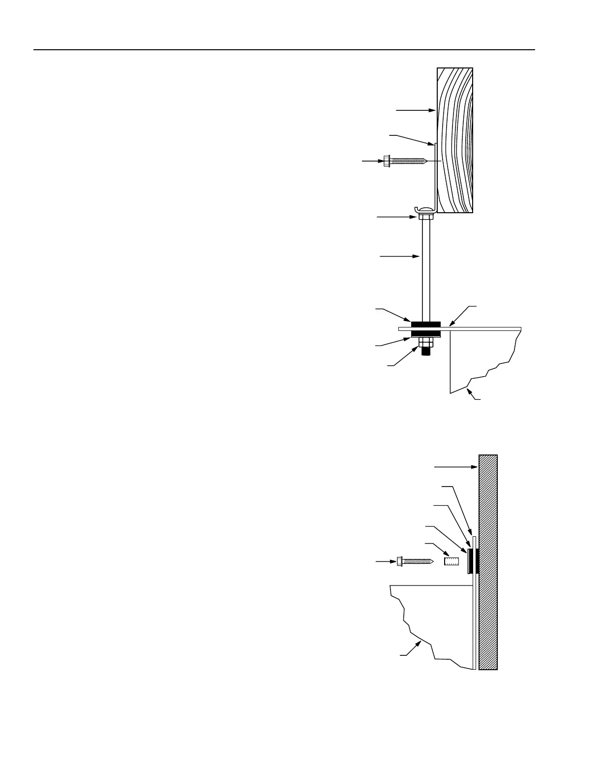
쐇 Insert a steel sleeve into each of the four mounting
strap bushings. See Fig. 5. With the cabinet mounted
horizontally, these bushings will be spaced 32 in. on
centers for direct attachment to wall studs spaced 16 in.
on centers. For other wall configurations, using of a
mounting board may be required.
쐋 Support the cabinet at the desired location and secure
with four no. 12 x 1-1/2 in. lag screws. The Fresh Air
Ventilation System is now mounted and ready for
attaching the ducting.
Wiring
Before wiring 240 Vac models, disconnect power supply to
prevent electrical shock or equipment damage. All wiring must
comply with local codes and ordinances.
120 Vac models are equipped with a line cord and a standard
3-prong plug that plugs into a wall outlet. See Fig. 6. 240 Vac
models, with frost control, require 240 Vac for the heater and
must be hardwired per the local electrical code. A neutral
must be connected to provide 120 Vac to the motors.
The Fresh Air Control is connected to the ventilator by six low
voltage wires. Wiring is one to one, two to two, etc., see Fig. 7.
Ter minal 2 on the Fresh Air Control is used as a tie point for
the optional remote switches; no factory wiring is connected
to this terminal.
FLOOR JOIST IN
BASEMENT CEILING
HANGING
BRACKET
HEX NUT
AND LOCKWASHER
1/4 20x6 BOLT
VIBRATION
DAMPENING BUSHING
WASHER
HEX NUTS (2)
MOUNTING
STRAP
CABINET
1-1/2 LAG SCREW (2)
M6127
Fig. 4. Typical mounting when suspending unit from
basement ceiling with four suspension bolts (one shown).
VIBRATION DAMPENING BUSHING
WASHER
UNIT MOUNTING STRAP
CABINET
1-1/2 LAG SCREW (2)
STEEL SLEEVE
MOUNTING SURFACE
M6128
Fig. 5. Typical mounting when unit is mounted to a wall
with four lag screws (one shown).
 Loading...