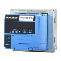
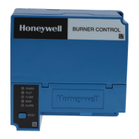
RM7838B,C 7800 SERIES RELAY MODULE
9 66-1094—08
a
See Table 2.
b
2000 VA maximum connected load to relay module.
c
Honeywell has tested this output at 9.8A at PF = 0.5, 58.A inrush for 100,000 cycles
d
Total load current, excluding Burner/Boiler Motor and Firing Rate Outputs cannot exceed 5A, 25A inrush.
e
Can also be 24Vac, 3A at PF = 0.5.
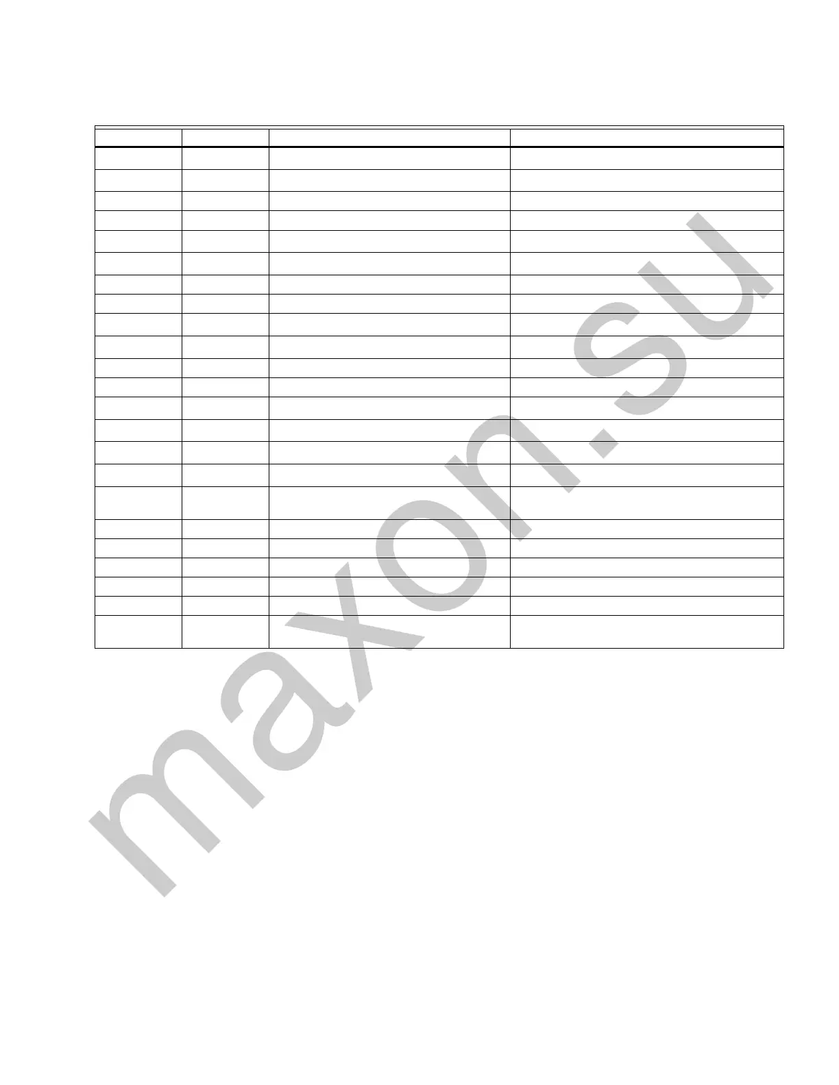
Table 7. RM7838C1020 Alternate Terminal Ratings
Terminal No. Abbreviation Description Ratings
G—
Flame Sensor Ground
a
—
Earth G —
Earth Ground
a
—
N — Line Voltage Common (Neutral) —
3 AL Alarm (Normally Open) 1A, 10A inrush for 5000 cycles
4 L1 Line Voltage Supply (L1)
120 Vac (+10/-15%), 50/60 Hz (+/-10%).
b
5 FAN Combustion Blower Motor
4A at PF =0.5, 20A inrush
c
6 — Stop Input 1mA
7 LD2 Airflow Switch Input (Lockout Interlock) 5A
8 pv1 Pilot Valve 1 (Interrupted)
4A at PF = 0.5, 20A inrush
d
9 MV Main Fuel Valve
4A at PF = 0.5, 20A inrush
d
10 IGN Ignition 2A at PF = 0.2
F(11) — Flame Sensor 60 to 220 Vac, current limited.
12 HI Firing Rate High Fire
0.5A at PF = 0.5
e
13 COM Firing Rate Common
0.5A at PF = 0.5
e
14 MOD Firing Rate Modulate
0.5A at PF = 0.5
e
15 LO Firing Rate Low FIre
0.5A at PF = 0.5
e
16 — Alarm (Normally Closed) 1A, 10A inrush for 5000 cycles; carry 5A for
250,000 cycles
17 —
18 ES1 Low Fire Switch Input 1mA
19 ES3 High Fire Switch Input 1mA
20 LOS Preignition Interlock 1mA
21 Start Switch Start Switch 1mA
22 SHTR Shutter Shutter drive for dynamic self-check flame
sensor.
 Loading...