WARNING
Improper configuration jumper selection could cause a fire or explosion hazard that could lead to property
damage, severe injury or death.
TABLE OF CONTENTS
Page
Honeywell R7795 ................................................................................................................................................................ 5
Honeywell R4795 ................................................................................................................................................................ 6
Honeywell RA890 ............................................................................................................................................................... 7
Honeywell R4140P.............................................................................................................................................................. 8
Honeywell R4140Y ............................................................................................................................................................. 9
Fireye UVM/TFM (all models)/M-SERIES II ............................................................................................................... 10
Fireye UVM—1 (prior to 1968) ..................................................................................................................................... 11
Fireye UVM—2 (prior to 1968) ..................................................................................................................................... 12
B.M. • 3-92 • ©Honeywell Inc. 1992 • Form Number 65-0125
CAUTION
1. Installer must be a trained, experienced, flame safeguard control service technician.
2. Disconnect power supply before beginning installation to prevent electrical shock and equipment damage. More
than one power supply disconnect may be involved.
3. All wiring must comply with applicable local electrical codes, ordinances, and regulations.
4. All line voltage terminal wiring shall be no. 14, 16 or 18 copper conductor TTW (60C) or THW (75C) or THHN
(90C), 600 volt insulation wire. A maximum of two conductors can be wired to each Q7800 Subbase terminal.
5. Voltage and frequency of the power supply and flame detector(s) connected to this control must agree with those
marked on the device.
6. Loads connected to the control terminals must not exceed ratings listed in Specification sheet 65-0086, or on the
RM7895 label.
7. All external timers must be listed or component recognized by authorities having jurisdiction for the specific purpose
for which they are used.
8. Perform all required checkout tests after installation is complete.
The diagrams and instructions contained in this booklet are for converting the following models of primaries
and programmers to RM7895 microprocessor based integrated burner control.
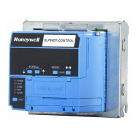
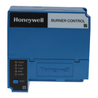
Conversion Wiring Diagrams
for RM7895