found to comply with the limits for a Class B computing
device of Part 15 of FCC rules which are designed to
provide reasonable protection against such interfer-
ence when operated in a commercial environment.
Operation of this equipment in a residential area may
cause interference, in which case, users at their own
expense may be required to take whatever measures
are required to correct this interference.
4. This digital apparatus does not exceed the Class B
limits for radio noise for digital apparatus set out on the
Radio Interference Regulations of the Canadian De-
partment of Communications.
APPROVAL BODIES:
Underwriters Laboratories Inc. listed: File No. MP268,
Guide No. MCCZ.
Canadian Standards Association certified: LR9S329-3.
Factory Mutual approved: Report No. JI1V9A0.AF.
Industrial Risk Insurers acceptable.
Federal Communications Commission, Part 15, Class B.
Canadian Department of Communications, CS-03, Certi-
fication No. 5733459A.
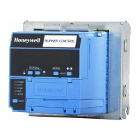
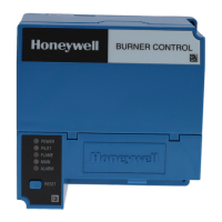
MOUNTING: Q7800A for panel mount or Q7800B for wall
or burner mount.
REQUIRED COMPONENTS:
Q7800 Subbase
ST7800 Purge Timer
RM7847/48/49/86 Flame Amplifier
ACCESSORIES:
5-Wire Connector
—part no. 203541.
Combustion Service Manager
—part no. ZM7850A1001.
Communication Interface Base Unit
—part no. Q7700A1014.
Communication Interface ControlBus Module
—part no. QS7800A1001.
2
DATA CONTROLBUS MODULE™
—part no. S7810A1009.
Dust Cover
—part no. 221729.
Electrical Access Slot Cover
—part no. 203765.
Expanded Annunciator
—part no. S7830A1005.
Flame Simulators
—part no. 203659 UV Flame Simulator.
—part no. 123514A Rectification Simulator.
Keyboard Display Module
—part no. S7800A1001.
Remote Display Mounting Bracket
—part no. 203765.
Remote Reset Module
—part no. S7820A1007.
Remote Display Power Supply
—part no. 203968 Plug-in.
—part no. 203969 Screw Terminal.
Tester
—part no. A7800A1002.
NORMAL OPERATION:
Main Flame
Establishing
Period
Device Initiate Standby Purge Pilot Main Run AFSC
1
DMV
2
RM7895A 10 sec. * ** 4 or 10 sec. * No No
RM7895B 10 sec. * ** 4 or 10 sec. * Yes No
RM7895C 10 sec. * ** 4 or 10 sec. 10 sec. * No Yes
RM7895D 10 sec. * ** 4 or 10 sec. 10 sec. * Yes Yes
* STANDBY and RUN can be an infinite time period.
** PURGE will be determined by which ST7800A Purge Card is selected.
1
AFSC - Airflow Switch Check
2
DMV - Delayed Main Valve
IMPORTANT:
1. For on-off gas-fired systems, some authorities having
jurisdiction prohibit the wiring of any limit or operat-
ing contacts in series between the flame safeguard
control and the main fuel valve(s).
2. Do not connect more than two C7012E,F or C7076A
Ultraviolet Flame Detectors (with self-checking shut-
ter) in parallel to the same terminals.
3. This equipment generates, uses and can radiate radio
frequency energy and if not installed and used in
accordance with the instructions may cause interfer-
ence to radio communications. It has been tested and
 Loading...