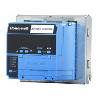
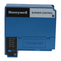
RM7895A,B,C,D/EC7895A,C; RM7896A,B,C,D 7800 SERIES RELAY MODULES
7 66-1090—06
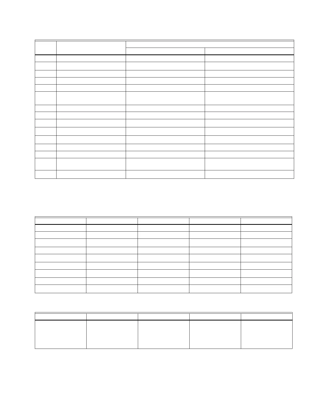
Table 3. Terminal Ratings.
a
See Table 2.
b
2000 VA maximum load connected to RM7895A,B,C,D/EC7895A,C/RM7896A,B,C,D Assembly.
c
See Tables 4 and 5.
d
Requires 220-240 Vac, 10 VA minimum, stepdown transformer to operate the shutter.
Table 4. Combinations for Terminals 8, 9, 10 and 21.
a
RM7895C,D: EC7895C, RM7896C,D only, jumper terminals 8 to 9.
Table 5. Composition of each Combination.
a
Pilot Duty refers to solenoid-type valves.
Terminal
Number Description
Ratings
RM7895/RM7896 EC7895
G Flame Sensor Ground — —
Earth G
Earth Ground
a
——
L2(N) Line Voltage Common — —
3 Alarm 120 Vac, 1A pilot duty. 220-240 Vac, 1A pilot duty.
4 Burner Motor 120 Vac, 9.8A AFL, 58.8 ALR (inrush). 220-240 Vac, 4A at PF = 0.5, 20A inrush.
5 Line Voltage Supply (L1) 120 Vac (+10/-15%), 50 or 60 Hz
(±10%).
b
220-240 Vac (+10/-15%), 50 or 60 Hz
(±10%).
6 Burner Controller and Limits 120 Vac, 1 mA. 220-240 Vac, 1 mA.
7 Lockout Interlock 120 Vac, 8A run, 43A inrush. 8A at PF = 0.5, 40A inrush, 2A at PF = 0.2.
8 Pilot Valve/Ignition
120 Vac
c
220-240 Vac, 4A at PF = 0.5, 20A inrush.
9 Main Fuel Valve
120 Vac
c
220-240 Vac, 4A at PF = 0.5, 20A inrush.
10 Ignition
120 Vac
c
220-240 Vac, 2A at PF = 0.2
F(11) Flame Sensor 60 to 220 Vac, current limited. 60 to 220 Vac, current limited.
12 to 20 Unused — —
21 2nd Stage Main Valve (EC7895C,
RM7895C,D; RM7896C,D)
120 Vac
c
220-240 Vac, 4A at PF = 0.5, 20A inrush.
22 Shutter 120 Vac, 0.5A
220-240 Vac
d
Combination Number Pilot Fuel 8 Main 9 Ignition 10 Delayed Main Valve 21
1 C F No Load No Load
2 B F No Load No Load
3
F
a
No Load A No Load
4FFANo Load
5
F
a
No Load A F
6 D F A No Load
7
D
a
No Load A D
8 DDANo Load
9
D
a
No Load A D
ABCDF
4.5A ignition
50 VA Pilot Duty
a
plus
4.5A ignition.
180 VA Ignition plus
motor valves with:
660 VA inrush,
360 VA open,
240 VA hold.
2A Pilot Duty.
a
65 VA Pilot Duty
a
plus
motor valves with:
3850 VA inrush,
700 VA open,
250 VA hold.
 Loading...