EasyManua.ls Logo

Honeywell RM7897A - User Manual

Honeywell RM7897A
20 pages
Print Icon
To Next Page IconTo Next Page
Loading...
INSTALLATION INSTRUCTIONS
32-00158-03
SIL
3
Capable
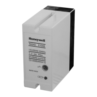
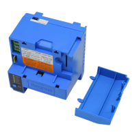
RM7897A,C 7800 SERIES
Relay Modules
APPLICATION
The RM7897A,C are microprocessor-based integrated
burner controls for automatically fired gas, oil, or
combination fuel single burner applications. The
RM7897A,C system consist of a relay module, subbase,
amplifier, and purge card. Options include: 2-line VFD (see
document 65-0090) or 4-line LCD (see document 32-
00110) Keyboard Display Module, Data ControlBus™
Module, remote display mounting, Expanded Annunciator
or Modbus module.
Functions provided by the RM7897A,C include automatic
burner sequencing, flame supervision, system status
indication, system or self-diagnostics and
troubleshooting.
The RM7897 adds a proof of closure input to the standard
primary control function of the RM7895/RM7896
product. It adds a blinking fault code function to the
POWER LED on Alarm shutdown. It also adds
programmable postpurge using the S7800A1142
Keyboard Display Module (KDM).
The RM7897A1002 offers selectable pilot operation,
intermittent on terminal 8 or interrupted on terminal 21.
The RM7897C1000 offers interrupted pilot and delayed
main valve for 2-step firing (Low-High-Low) applications.
The RM7897C1018 has 4 second MFEP (main flame
establishing period).
The RM7897C1026 provides a special recycle function for
configuration of Jumper JR2:
JR 2 intact: Recycle on loss of flame.
JR2 clipped: If flame loss occurs during the first 15
seconds in the Run period, then lockout occurs. If
flame loss occurs after 15 seconds into the Run
period, then recycle.
Factory default for Post Purge time: 15 seconds.
This document provides installation and static checkout
instructions. Other applicable publications are:
This document covers the following 7800 Series Relay
Modules:
RM7897A1002
RM7897A2002
RM7897C1000
RM7897C2000
SPECIFICATIONS
Electrical Ratings (See Table 3):
Voltage and Frequency:
RM7897A,C: 120 Vac (+10/-15%), 50/60 Hz (± 10%).
Power Dissipation: 10W maximum.
Maximum Total Connected Load: 2000 VA.
Fusing Total Connected Load: 15A Fast Blow, type SC or
equivalent.
Environmental Ratings:
Ambient Temperature:
Operating: -40°F to 140°F (-40°C to +60°C).
Storage: -40°F to 150°F (-40°C to +66°C).
Publication
No. Product
32-00110 S7800A2142 4-line LCD Keyboard Display
Module Product Data
65-0084 Q7800A,B 22-Terminal Wiring Subbase
Product Data
65-0288 S7800A1142 Keyboard Display Module
Product Data
65-0091 S7810A Data ControlBus Module™ Product
Data
65-0095 S7820 Remote Reset Module Product Data
65-0097 221729C Dust Cover Installation
Instructions
65-0101 S7830 Expanded Annunciator Product Data
65-0109 R7824, R7847, R7848, R7849, R7851,
R7852, R7861, R7886 Flame Amplifiers for
the 7800 Series Product Data
65-0131 221818A Extension Cable Assembly
Product Data
65-0229 7800 SERIES Relay Modules Checkout and
Troubleshooting Product Data.
Question and Answer IconNeed help?

Do you have a question about the Honeywell RM7897A and is the answer not in the manual?

Overview

The Honeywell RM7897A,C 7800 Series Relay Modules are microprocessor-based integrated burner controls designed for automatically fired gas, oil, or combination fuel single burner applications. These modules are part of a system that includes a relay module, subbase, amplifier, and purge card, with options for a 2-line VFD or 4-line LCD Keyboard Display Module (KDM), Data ControlBus™ Module, remote display mounting, Expanded Annunciator, or Modbus module.

Function Description:

The RM7897A,C modules provide automatic burner sequencing, flame supervision, system status indication, and system or self-diagnostics with troubleshooting capabilities. The RM7897 adds a proof of closure input to the standard primary control functions of the RM7895/RM7896 products. It also features a blinking fault code function on the POWER LED during alarm shutdowns and programmable postpurge using the S7800A1142 KDM.

Specific models offer distinct functionalities:

  • RM7897A1002: Offers selectable pilot operation, either intermittent on terminal 8 or interrupted on terminal 21.
  • RM7897C1000: Provides interrupted pilot and delayed main valve for 2-step firing (Low-High-Low) applications.
  • RM7897C1018: Features a 4-second Main Flame Establishing Period (MFEP).
  • RM7897C1026: Includes a special recycle function based on Jumper JR2 configuration:
    • JR2 intact: Recycles on loss of flame.
    • JR2 clipped: If flame loss occurs during the first 15 seconds of the Run period, a lockout occurs. If flame loss occurs after 15 seconds into the Run period, it recycles. The factory default for Post Purge time is 15 seconds.

Important Technical Specifications:

  • Electrical Ratings:
    • Voltage and Frequency: 120 Vac (+10%/-15%), 50/60 Hz (±10%).
    • Power Dissipation: 10W maximum.
    • Maximum Total Connected Load: 2000 VA.
    • Fusing Total Connected Load: 15A Fast Blow, type SC or equivalent.
  • Environmental Ratings:
    • Operating Ambient Temperature: -40°F to 140°F (-40°C to +60°C).
    • Storage Ambient Temperature: -40°F to 150°F (-40°C to +66°C).
    • Humidity: 85% relative humidity continuous, non-condensing.
    • Vibration: 0.5G environment.
  • SIL 3 Capable: The device is SIL 3 capable in a properly designed Safety Instrumented System.
  • Approvals: Underwriters Laboratories Inc. Listed (File No. MP268, Guide No. MCCZ), Factory Mutual Approved (Report No. 1V9A0.AF), Swiss RE (formerly IRI) Acceptable, Federal Communications Commission (Part 15, Class B, Emissions).
  • Wire Sizes: Recommended wire sizes vary by application, including 14, 16, or 18 AWG copper for line voltage terminals, and 22 AWG two-wire twisted pair with ground for Keyboard Display Module, Data ControlBus™ Module, and Remote Reset Module.
  • Maximum Wire Lengths:
    • RM7897A,C leadwires: 300 feet to terminal inputs.
    • Flame Detector leadwires: Limited by flame signal strength.
    • Remote Reset leadwires: 1000 feet (305 meters).
    • Data ControlBus™ Module: Up to 4000 feet (1219 meters) interconnecting wire, depending on the number of modules, noise conditions, and cable used.

Usage Features:

  • Installation: Requires careful reading of instructions, checking ratings, and installation by a trained, experienced flame safeguard service technician. Proper subbase wiring is crucial, with specific compatibility notes for Series 1000 and Series 2000 subbases. Subbases can be mounted in any position except horizontally with bifurcated contacts pointing down.
  • Safety Precautions: Warnings for fire/explosion and electrical shock hazards are emphasized. Disconnecting power before installation is mandatory. All wiring must comply with applicable codes and regulations.
  • System Components: The relay module integrates with various other components like the KDM, flame amplifier, and purge timer.
  • Post Purge Setup: An S7800A1142 KDM is required to set up the programmable Post Purge Timing. The setup involves navigating through the KDM display, entering a password, and adjusting the time in 1-second, 10-second, or 1-minute intervals. The setting is programmed into the relay module by pressing and holding the reset button for five seconds.
  • Run/Test Switch: Located on the top side of the relay module, this switch alters the burner sequence. In the TEST position, it can stop PREPURGE timing or the timer during the Pilot Flame Establishing Period (PFEP), allowing for pilot turn-down tests and other burner adjustments.
  • Selectable Site-Configurable Jumpers: Three jumpers (JR1, JR2, JR3) allow customization of PFEP duration, flame failure action, and airflow switch (ILK) failure response. Clipping and removing a jumper enhances safety but can cause a nonresettable Fault 110 if done after 200 hours of operation, requiring module replacement.

Maintenance Features:

  • Static Checkout: A comprehensive static checkout procedure is provided to verify correct wiring of the Q7800 Wiring Subbase and proper operation of external controllers, limits, interlocks, actuators, valves, transformers, motors, and other devices before installing the relay module.
  • Troubleshooting: The POWER LED provides fault identification through a series of fast- and slow-blinking lights, representing fault codes. A detailed table of blinking fault codes and recommended troubleshooting steps is included to diagnose system failures such as low AC line voltage, unexpected flame signals, flame signal absent, flame signal overrange, running/lockout interlock problems, VPS (Valve Proving Switch) issues, purge card problems, wiring problems, flame amplifier problems, configuration jumper problems, preignition interlock faults, high/low fire switch failures, man-open switch/start switch/control on issues, and internal self-test failures.
  • Reset: Manual reset is required after any safety shutdown, achievable by pressing the push button on the device, a remote reset wired through an attached display, or an S7820 remote reset module. Interrupting power causes electrical resets but does not reset a safety shutdown (lockout) condition.
  • Physical Device Protection: Device access should be limited to authorized personnel, and installation in publicly accessible places is not recommended. Locking the device in an enclosed cabinet and physically securing all wiring is advised. The Run/Test switch label/seal is intended to prevent and detect unauthorized access.
  • Modbus & DDL Interface Security: Critical conducts for device functionality (DDL, Modbus lines) must be physically protected. Modbus RS-485 & DDL protocols do not support security features; only DDL devices should be connected to the Burner Controller DDL line.

Honeywell RM7897A Specifications

General IconGeneral
BrandHoneywell
ModelRM7897A
CategoryRelays
LanguageEnglish

Related product manuals