44 ซ.บรมราชชนนี 70 ถ.บรมราชชนนี ศาลาธรรมสพน์ ทวีวัฒนา กทม. 10170.
Website: https://www.add-furnace.com/ โทร: 02-888-3472
Line ID: @add11 e-mail: add028883472@gmail.com
TROUBLESHOOTING
❏
Energize the module and immediately touch one end of
the jumper firmly to the GND terminal on the module. Move
the free end of the jumper slowly toward the SPARK
terminal until a spark is established.
❏
Pull the jumper slowly away from the terminal and note
the length of the gap when sparking stops. Check table
below.
Perform the checkout on page 11 as the first step in
troubleshooting. Then check the appropriate troubleshoot-
ing guide (Fig. 14 or 15) and the schematic diagram (Figs.
16-17) to pinpoint the cause of the problem. If troubleshoot-
ing indicates an ignition problem, see Ignition System
Checks below to isolate and correct the problem.
Following troubleshooting, perform the checkout proce-
dure (page 11) again to be sure system is operating
normally.
IGNITION SYSTEM CHECKS
STEP 1: Check ignition cable.
Make sure:
❏
Ignition cable does not run in contact with any metal
surfaces.
❏
Ignition cable is no more than 36 in. [0.9 m] long.
❏
Connections to the ignition module and to the igniter or
igniter-sensor are clean and tight.
❏
Ignition cable provides good electrical continuity.
STEP 2: Check ignition system grounding. Nuisance shut-
downs are often caused by a poor or erratic ground.
❏
A common ground, usually supplied by the pilot burner
bracket, is required for the module and the pilot burner/
igniter-sensor.
•
Check for good metal-to-metal contact between the
pilot burner bracket and the main burner.
•
Check the ground lead from the GND(BURNER)
terminal on the module to the pilot burner. Make sure
connections are clean and tight. If the wire is dam-
aged or deteriorated, replace it with No. 14-18 gauge,
moisture-resistant, thermoplastic insulated wire with
105
C [221
F] minimum rating.
—
Check the ceramic flame rod insulator for cracks
or evidence of exposure to extreme heat, which
can permit leakage to ground. Replace pilot burner/
igniter-sensor and provide shield if necessary.
—
If flame rod or bracket are bent out of position,
restore to correct position.
STEP 3: Check spark ignition circuit. You will need a short
jumper wire made from ignition cable or other heavily
insulated wire.
❏
Close the manual gas valve.
❏
Disconnect the ignition cable at the SPARK terminal on
the module.
STEP 4: Check pilot and main burner lightoff.
❏
Set the thermostat to call for heat.
❏
Watch the pilot burner during the ignition sequence. See
if:
•
Ignition spark continues after the pilot is lit.
•
The pilot lights and the spark stops, but main burner
does not light.
•
S8600B,H,M; S8610B,H; S8660D; S8670D only: The
pilot lights, the spark stops and main burner lights, but
the system shuts down.
❏
If so, ensure adequate flame current as follows.
•
Turn off furnace at circuit breaker or fuse box.
•
Clean the flame rod with emery cloth.
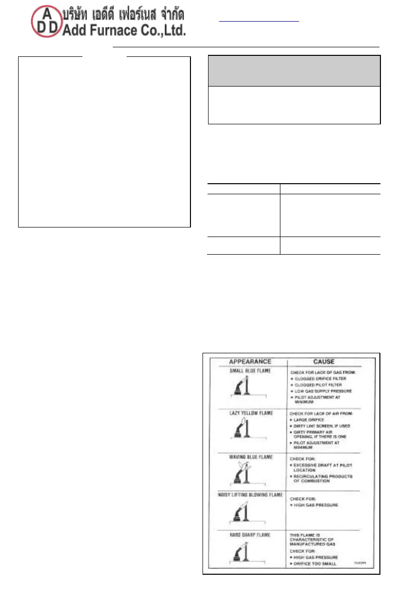
Fig. 13—Examples of unsatisfactory pilot flames.
When performing the following steps, do not touch
stripped end of jumper or SPARK terminal. The
ignition circuit generates over 10,000 volts and
electrical shock can result.
IMPORTANT
1.
The following service procedures are provided as
a general guide. Follow appliance manufacturer’s
service instructions if available.
2.
On lockout and retry models, meter readings
between gas control and ignition module must be
taken within the trial for ignition period. Once the
ignition module shuts off, lockout models must be
reset by setting the thermostat down for at least
one minute before continuing. On retry models,
wait for retry or reset at the thermostat.
3.
If any component does not function properly,
make sure it is correctly installed and wired before
replacing it.
4.
The ignition module cannot be repaired. If it mal-
functions, it must be replaced.
5.
Only trained, experienced service technicians
should service intermittent pilot systems.
No arc or arc less
than 1/8 in. [3 mm]
Check external fuse, if provided.
Verify power at module input
terminal.
Replace module if fuse and
power ok.
Arc 1/8 in. [3 mm]
or longer.
 Loading...


