EasyManuals Logo

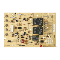
Honeywell ST9103A User Manual

Honeywell ST9103A
12 pages
To Next Page IconTo Next Page
To Previous Page IconTo Previous Page
Page #2 background imageLoading...
Page #2 background image
2
S9103A ELECTRONIC FAN TIMER
69-0771B
Fig. 1. Typical ST9103A wiring connections.
THERMOSTAT
R
GYW
R
Y
C
W
G
LO
ML
MH
HI
CIRCULATING
FAN
STARTING
CAP
X
C
24
VAC
120
VAC
M5551
C
O
O
L
C
O
N
T
E
A
C
B
U
R
N
E
R
UNUSED
MOTOR
123
4
5
67
BURNER
MOTOR
ST9103
L1
L2
ORANGE
T1 T2
(BLACK)
(WHITE)
R8991
OIL PRIMARY CONTROL
FLAME DETECTOR
CAD CELL
1
INTERLOCK
FUSE
LIMIT
CONTROL
H
E
A
T
3
12
1
DENOTES STANDARD TERMINAL.
DENOTES OPTIONAL TERMINAL.
1
L2 (N)
L1 (H)
TO 120 VAC
POWER SUPPLY
H
U
M
NOTE:
DENOTES LINE VOLTAGE CONNECTIONS.
DENOTES LOW VOLTAGE CONNECTIONS.

Questions and Answers:

Question and Answer IconNeed help?

Do you have a question about the Honeywell ST9103A and is the answer not in the manual?

Honeywell ST9103A Specifications

General IconGeneral
BrandHoneywell
ModelST9103A
CategoryFan
LanguageEnglish

Related product manuals