T775A/B/M SERIES 2000 ELECTRONIC STAND-ALONE CONTROLLERS
21 62-0254—13
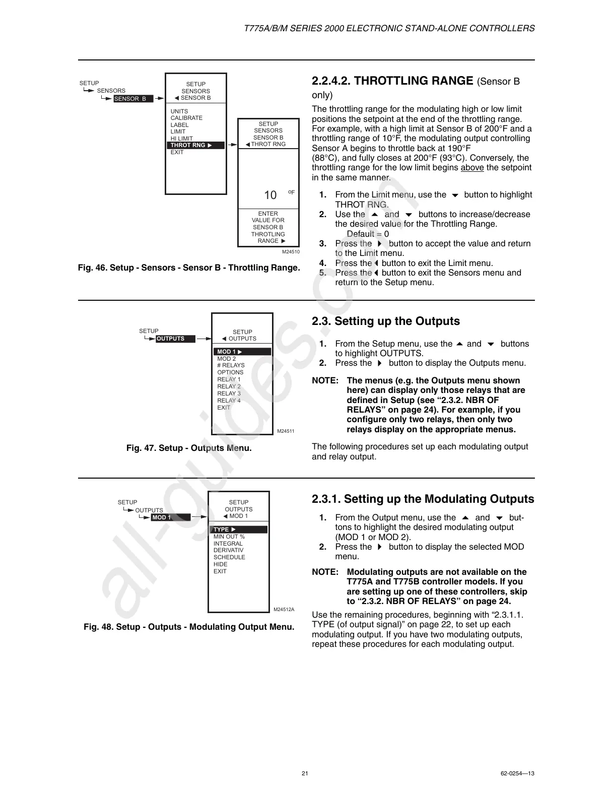
Fig. 46. Setup - Sensors - Sensor B - Throttling Range.
2.2.4.2. THROTTLING RANGE (Sensor B
only)
The throttling range for the modulating high or low limit
positions the setpoint at the end of the throttling range.
For example, with a high limit at Sensor B of 200°F and a
throttling range of 10°F, the modulating output controlling
Sensor A begins to throttle back at 190°F
(88°C), and fully closes at 200°F (93°C). Conversely, the
throttling range for the low limit begins above
the setpoint
in the same manner.
1. From the Limit menu, use the button to highlight
THROT RNG.
2. Use the
and buttons to increase/decrease
the desired value for the Throttling Range.
Default = 0
3. Press the
button to accept the value and return
to the Limit menu.
4. Press the
button to exit the Limit menu.
5. Press the
button to exit the Sensors menu and
return to the Setup menu.
Fig. 47. Setup - Outputs Menu.
2.3. Setting up the Outputs
1. From the Setup menu, use the and buttons
to highlight OUTPUTS.
2. Press the
button to display the Outputs menu.
NOTE: The menus (e.g. the Outputs menu shown
here) can display only those relays that are
defined in Setup (see “2.3.2. NBR OF
RELAYS” on page 24). For example, if you
configure only two relays, then only two
relays display on the appropriate menus.
The following procedures set up each modulating output
and relay output.
Fig. 48. Setup - Outputs - Modulating Output Menu.
2.3.1. Setting up the Modulating Outputs
1. From the Output menu, use the and but-
tons to highlight the desired modulating output
(MOD 1 or MOD 2).
2. Press the
button to display the selected MOD
menu.
NOTE: Modulating outputs are not available on the
T775A and T775B controller models. If you
are setting up one of these controllers, skip
to “2.3.2. NBR OF RELAYS” on page 24.
Use the remaining procedures, beginning with “2.3.1.1.
TYPE (of output signal)” on page 22, to set up each
modulating output. If you have two modulating outputs,
repeat these procedures for each modulating output.
 Loading...