T775U SERIES 2000 CONTROLLER 1. SETUP
62-0255–05 14
Setup Procedure
The Setup process uses a hierarchical menu structure
that is easy to use. You press the W and X arrow buttons
to move forward and backward through the menus.
NOTE: The menus can display only those relays that
are defined in Setup (see “1.3.2. NBR OF
RELAYS” on page 21). For example, if you con-
figure only two relays, then only two relays dis-
play on the appropriate menus.
To change the controller’s sensors and output setup
parameters, perform the following procedures in the order
listed:
1. Enter Setup mode — see “1.1. Entering Setup
Mode”
2. Setup Sensors — see “1.2. Setting up the Sensors”
3. Setup Outputs — see “1.3. Setting up the Outputs”
on page 17
4. Exit Setup Mode — see “1.4. Exiting Setup” on
page 24
1.1. Entering Setup Mode
To enter Setup mode, press and hold the MENU button
for five seconds to display the Setup menu. See Fig. 23
on page 12.
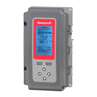
Fig. 24. Setup - Sensors Menu.
1.2. Setting up the Sensors
1. From the Setup menu, use the S and T buttons to
highlight SENSORS.
2. Press the X button to display the Sensors menu.
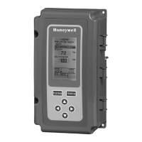
Fig. 25. Setup - Sensors - Number of Sensors.
1.2.1. Number of SENSORS
The value entered here determines the number of
sensors displayed on the home screen.
NOTE: For applications that do not use Reset, only one
sensor (Sensor A) is available for use.
1.
From the Sensors menu, highlight # SENSORS then
press the
X
button to display the number of sensors.
2. Use the S and T buttons to enter the number of
sensors (1 or 2).
Default: 2
3. Press the X button to accept the value and display
the SENSOR A selection.
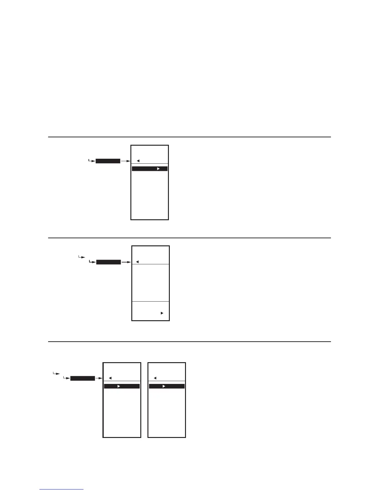
Fig. 26. Setup - Sensors - Sensor A Menu.
1.2.2. SENSOR A
If you are implementing two-sensor reset control, Sensor A
must always be the controlled temperature and Sensor B must
always be the controlling temperature. For example, in a reset
control based on outside temperature, Sensor A must be the
inside sensor and Sensor B must be the outside sensor.
1. From the Sensors menu, highlight SENSOR A.
2. Press the X button to display the Sensor A selec-
tions.
The menu selections change depending on whether the
sensor type is 1097Ω PTC (temperature) or 0-10V / 4-
20MA.
SETUP
SENSORS
SETUP
SENSORS
# SENSORS
SENSOR A
SENSOR B
EXIT
M24586
ENTER
NUMBER OF
SENSORS
SETUP
SENSORS
# SENSORS
SETUP
SENSORS
# SENSORS
2
M24587
SETUP
SENSORS
SENSOR A
SETUP
SENSORS
SENSOR A
TYPE
UNITS
CALIBRATE
LABEL
EXIT
SETUP
SENSORS
SENSOR A
TYPE
UNITS
MIN VAL
MAX VAL
CALIBRATE
LABEL
EXIT
SENSOR A
TYPE = PT1000
SENSOR A
TYPE = 0-5V, 0-10V,
OR 4-20MA
M24588A

 Loading...