T8411R ELECTRONIC HEAT PUMP THERMOSTAT
68-0185—2 6
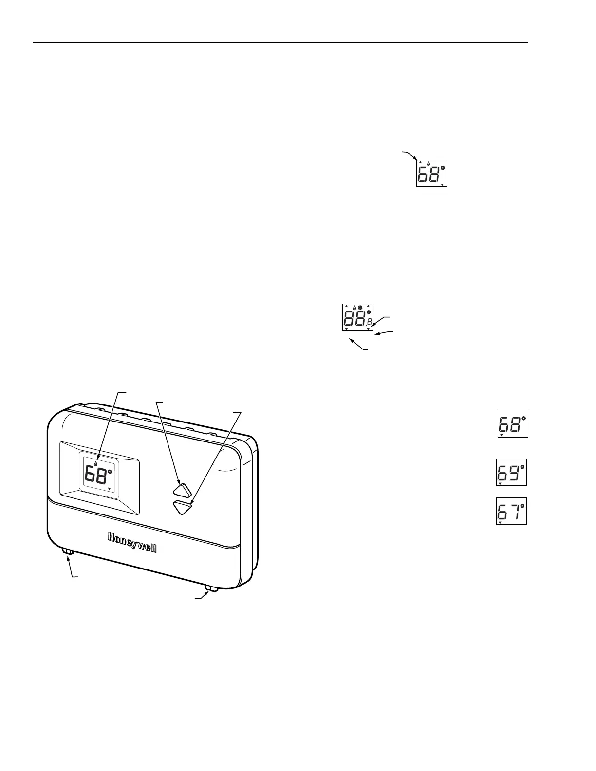
SETTINGS AND ADJUSTMENTS
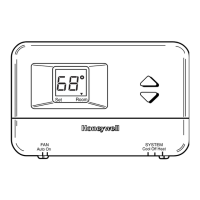
Setting Fan and System Switches
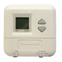
Fan and system settings are controlled manually using the
switches located at the bottom of the thermostat case. See
Fig. 8.
Fan Switch
Fan switch settings are:
On: The fan runs continuously. Use for improved air circu-
lation.
Auto: Normal setting for most homes. The fan starts and
stops with the equipment.
Slide the switch in the bottom left corner of the thermostat to
select the desired fan setting.
System Switch
System switch settings control thermostat operation as follows:
Cool: The thermostat controls the cooling system.
Heat: The thermostat controls the heating system.
Off: Both heating and cooling are off.
Em. Ht: Thermostat cycles auxiliary heat (W2) and emer-
gency heat relay (E) as needed to maintain setpoint.
Terminal L is energized continuously. (Fault heat relay is
on continuously.) Cooling system is off. Compressor is
de-energized.
Slide the switch in the bottom right corner of the thermostat to
select the desired system setting.
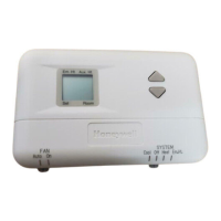
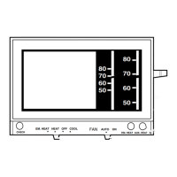
Fig. 8. Temperature display and system switches.
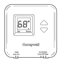
Em Ht and Aux Ht Indications
The ▲ indicator points to either Emergency Heat (Em Ht) or
Auxiliary Heat (Aux Ht) when these modes are active.
Em Ht: The ▲ indicator points to Em Ht when the SYSTEM
switch is set at Em Ht.
Aux Ht: The ▲ indicator points to Aux Ht when auxiliary
backup heat is needed to help handle the heating load.
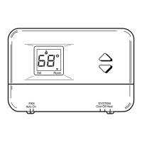
Set Temperature Setpoint
NOTE: Temperature setpoint range is 40° to 99°F (4° to 39°C).
The temperature setpoint and the room temperature are
shown separately on the display. The ▼ indicator points to Set
when the temperature setpoint is displayed and to Room
when the room temperature is displayed.
To set temperature setpoint:
1. Select Heat or Cool by sliding the SYSTEM switch in
the lower right corner of the thermostat to the desired
mode. See Fig. 8.
2. To display the selected temperature setpoint
on the digital display, press either the ▲ or ▼
key once. The temperature setpoint is dis-
played for approximately five seconds as the
indicator points to Set and flashes.
3. To increase the temperature setpoint, press
the ▲ key. Each press changes the setpoint
one degree; press and hold to change the
setpoint several degrees.
4. To decrease the temperature setpoint, press
the ▼ key. Each press changes the setpoint
one degree; press and hold to change the
setpoint several degrees.
Setting °F/°C Indication and Heat Cycle Rate
NOTE: To save changes to the °F/°C indication and the heat
cycle rate, all seven steps must be completed.
In installer setup mode steps 2. through 5., each
press of the ▲ key momentarily displays 01 and
each press of the ▼ key momentarily displays 02.
When the keys are released, these two-digit codes
are no longer displayed.
SYSTEM
Cool Off Heat Em Ht
Auto On
FAN
M18542
TEMPERATURE DISPLAY
INCREASE SETTING
DECREASE SETTING
FAN SWITCH
SYSTEM SWITCH
Em Ht Aux Ht
Set Room
Set
Room
NDICATOR
M18425
Em Ht
et
Room
INDICATOR
ROOM TEMPERATURE
SETPOINT TEMPERATURE
M1467
M1468
M1468
M1468
 Loading...