Honeywell
T841A
Heating-Cooling Thermostats
INSTALLATION INSTRUCTIONS
APPLICATION
The T841A Thermostats provide 24 Vac control of two-
stage heating and one-stage cooling in heat pump
systems using manual changeover.
The T841A provides EM.HT.-HEAT-OFF-COOL system
switching and AUTO-ON fan switching.
Test holes are provided on the front of the thermostat to
accommodate test meter leads without removing the
thermostat from the wall. Remove the cover of the
thermostat to expose test holes that are labeled to
correspond with the terminals on the back of the thermostat.
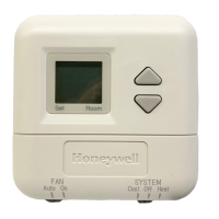
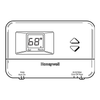
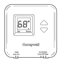
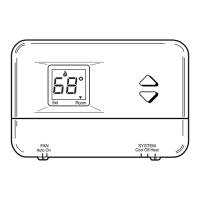
Table 1. Thermostat Features.
Thermostat
Terminal
Designations LEDs
Auto Fan in
EM. HT.
Figure
Numbers
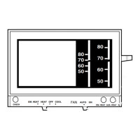
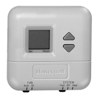
T841A W3, W2, Y, G, R, E, X, O, B, L AUX. HT., EM. HT., CHECK Yes 2
W3, W2, Y, G, R, E, X, O, B, L AUX. HT., EM. HT. Yes 3, 4
W, Y, R, T, F, G, X2, O, B EM. HT., AUX. HT. Yes 5
W3, W2, Y, G, R, E, X, O, B
—
Yes 6
W3, W2, Y, G, R, E, X, O, B EM. HT., AUX. HT. Yes 7
W2, W1, Y1, G, R, E, X, O, B EM. HT., AUX. HT. Yes 8
W3, W2, Y, G, R, E, X, O, B EM. HT., AUX. HT. Yes 9
W2, W1, Y, G, R, K, Z, X EM. HT., SERVICE No 10
W2, H, Y, G, R, E, X, A, O, B EM. HT., COMP. FAULT No 11
W, Y, G, R, X, O, B EM. HT., AUX. HT. Yes 12
W2, W1, Y1, G, R, E, X, O, B, L EM. HT., AUX. HT. Yes 13
W2, W1, Y, G, R, E, C/X, O, B, EM. HT., AUX. HT. Yes 14
W, Y, G, R, T, F, X2, O, B, U EM. HT., AUX. HT. Yes 15
W2, Y, G, R, E, B, X
—
Yes 16
OPERATION
The stages of heat make sequentially as the temperature
drops. Make refers to the mercury switch initiating a call for
heat or cool.
There is about 1 °F (0.6°C) between stages so the second
stage (auxiliary heat) makes only when the first stage
cannot handle the load. This 1°F is the interstage
differential.
The light emitting diode (LED) indicators on certain
thermostat models light when something specific happens
within the system. The AUX. HT. LED lights when auxiliary
heat (second stage heat) is operating due to extremely
cold weather that requires additional heat to supplement
the heat pump. When the red EM. HT. LED lights, the
emergency heat is operating (usually electric strip
heaters), because the homeowner has physically switched
to the EM. HT. position. When the red CHECK LED lights,
it indicates that something needs to be done to maintain
efficient system operation. See heating/cooling
manufacturer's instructions for specific meaning. When the
yellow COMP. FAULT LED lights, a compressor problem
requires attention. When the yellow SERVICE LED lights,
see heating/cooling manufacturer's instructions for specific
meaning.
C o p y rig h t © 1 9 9 8 H o ney w e ll Inc. All R igh ts R e se r v e d
69-1218