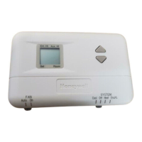
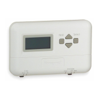
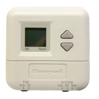
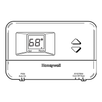
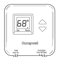
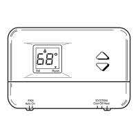
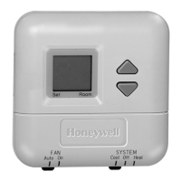
T841A HEATING-COOLING THERMOSTATS
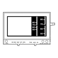
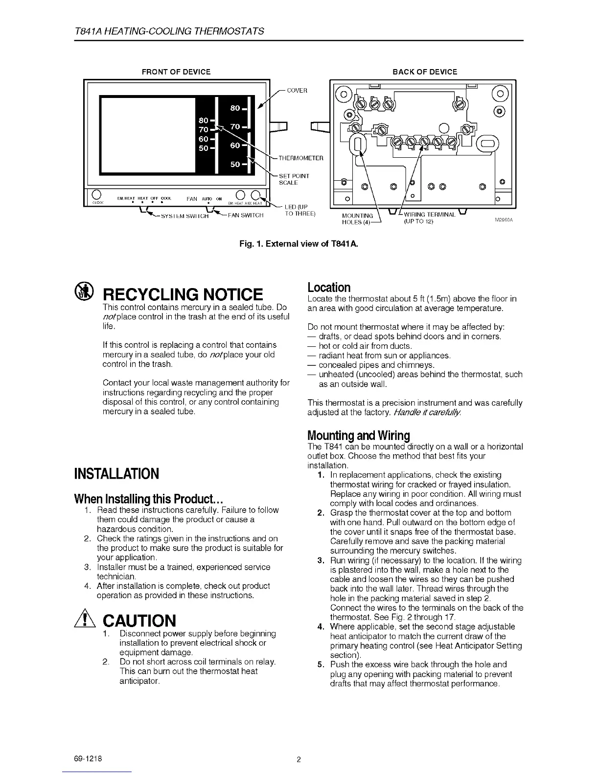
F R O N T O F D E V IC E B A C K O F D E V IC E
-S YS TE M SWITCH
FAN SWITCH
THERMOMETER
SET POINT
SCALE
- LED (UP
TO THREE)
MOUNTING
HOLES (4)
L WIRING TERMINAL 1
(UP TO 12)
COVER
Fig. 1. External view of T841A.
® RECYCLING NOTICE
This control contains mercury in a sealed tube. Do
ntplace control in the trash at the end of its useful
life.
If this control is replacing a control that contains
mercury in a sealed tube, do ntplace your old
control in the trash.
Contact your local waste management authority for
instructions regarding recycling and the proper
disposal of this control, or any control containing
mercury in a sealed tube.
INSTALLATION
When Installing this Product...
1. Read these instructions carefully. Failure to follow
them could damage the product or cause a
hazardous condition.
2. Check the ratings given in the instructions and on
the product to make sure the product is suitable for
your application.
3. Installer must be a trained, experienced service
technician.
4. After installation is complete, check out product
operation as provided in these instructions.
A CAUTION
1. Disconnect power supply before beginning
installation to prevent electrical shock or
equipment damage.
2. Do not short across coil terminals on relay.
This can burn out the thermostat heat
anticipator.
Location
Locate the thermostat about 5 ft (1.5m) above the floor in
an area with good circulation at average temperature.
Do not mount thermostat where it may be affected by:
— drafts, or dead spots behind doors and in corners.
— hot or cold air from ducts.
— radiant heat from sun or appliances.
— concealed pipes and chimneys.
— unheated (uncooled) areas behind the thermostat, such
as an outside wall.
This thermostat is a precision instrument and was carefully
adjusted at the factory. Handle it carefully.
Mounting and Wiring
The T841 can be mounted directly on a wall or a horizontal
outlet box. Choose the method that best fits your
installation.
1. In replacement applications, check the existing
thermostat wiring for cracked or frayed insulation.
Replace any wiring in poor condition. All wiring must
comply with local codes and ordinances.
2. Grasp the thermostat cover at the top and bottom
with one hand. Pull outward on the bottom edge of
the cover until it snaps free of the thermostat base.
Carefully remove and save the packing material
surrounding the mercury switches.
3. Run wiring (if necessary) to the location. If the wiring
is plastered into the wall, make a hole next to the
cable and loosen the wires so they can be pushed
back into the wall later. Thread wires through the
hole in the packing material saved in step 2.
Connect the wires to the terminals on the back of the
thermostat. See Fig. 2 through 17.
4. Where applicable, set the second stage adjustable
heat anticipator to match the current draw of the
primary heating control (see Heat Anticipator Setting
section).
5. Push the excess wire back through the hole and
plug any opening with packing material to prevent
drafts that may affect thermostat performance.
69-1218
2
 Loading...