T841A HEATING-COOLING THERMOSTATS
6. L o o s e ly secure the the rm osta t to the w all o r outlet
b o x w ith scre w s th rough the tw o m o un tin g h o le s in
the m iddle of th e dev ice. T h e shee tm eta l screw s
in clu ded w ith the th e rm o s tat are d e s ig n e d fo r use in
a p laste r w a ll and a nch o rs are not needed.
7. Level the therm o s tat e x actly u sing a spirit level or
plu m b line. T ig h te n the tw o m o untin g scre w s at the
m id d le of the device.
8. Install tw o sc re w s in the to p m o untin g hole s and
tighte n.
IMPORTANT
An incorrectly leveled subbase will cause the
temperature control to deviate from setpoint. It is
not a calibration problem.
9. R eplace the th erm o s tat cover.
ODT 1
L1
(HOT)
L2
CHANGEOVER
RELAY (COOL)
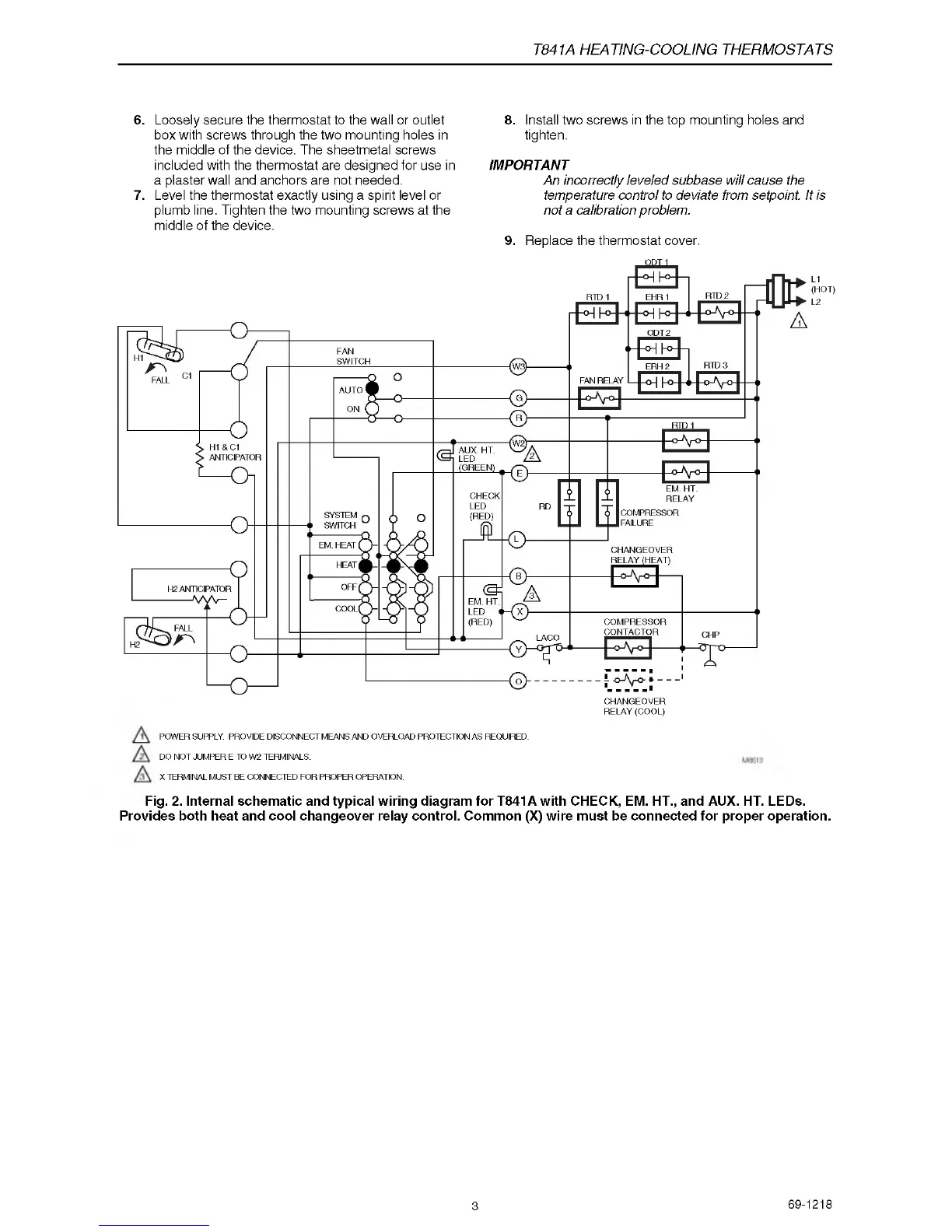
POWER SUPPLY. PROVIDE DISCONNECT MEANS AND OVERLOAD PROTECTION AS REQUIRED.
DO NOT JUMPER E TO W2 TERMINALS.
X TERMINAL MUST BE CONNECTED FOR PROPER OPERATION.
Fig. 2. Internal schematic and typical wiring diagram for T841A with CHECK, EM. HT., and AUX. HT. LEDs.
Provides both heat and cool changeover relay control. Common (X) wire must be connected for proper operation.
3
69-1218
 Loading...