T841A HEATING-COOLING THERMOSTATS
ODT 1
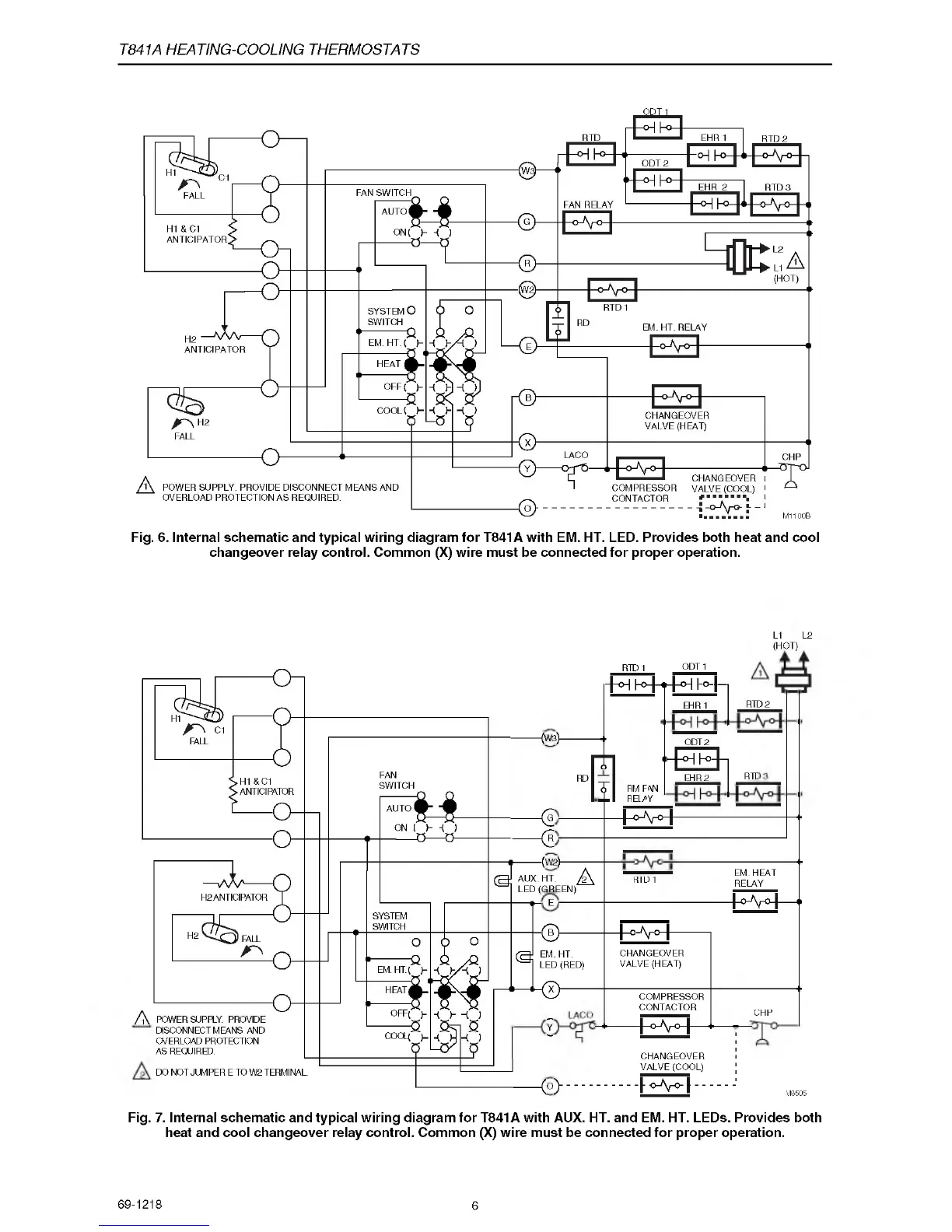
Fig. 6. Internal schematic and typical wiring diagram for T841A with EM. HT. LED. Provides both heat and cool
changeover relay control. Common (X) wire must be connected for proper operation.
DISCONNECT MEANS AND
OVERLOAD PROTECTION
AS REQUIRED.
DO NOT JUMPER E TO W2 TERMINAL.
L1 L2
(HOT)
^W 3 )-
a
< R
•(W 2)-
AUX. HT.
LED (GREEN)
E
a y
RTD 1 ODT 1
J-°H hH-T-HH l~°-|-|
EHR 1 RTD 2
ODT 2
m -TEEh
EHR 2 RTD
y r m a t
J-°-V H
------------
A
EM. HT.
LED (RED)
< X h
Y
< c > - -
EM .HEAT
RELAY
-A V H — "
+ ° - V ° +
CHANGEOVER
VALVE (HEAT)
COMPRESSOR
CONTACTOR
+ >V H —
CHANGEOVER
VALVE (COOL)
T<>v>|
Fig. 7. Internal schematic and typical wiring diagram for T841A with AUX. HT. and EM. HT. LEDs. Provides both
heat and cool changeover relay control. Common (X) wire must be connected for proper operation.
RD
RID 1
CHP
M8505
69-1218
6
 Loading...