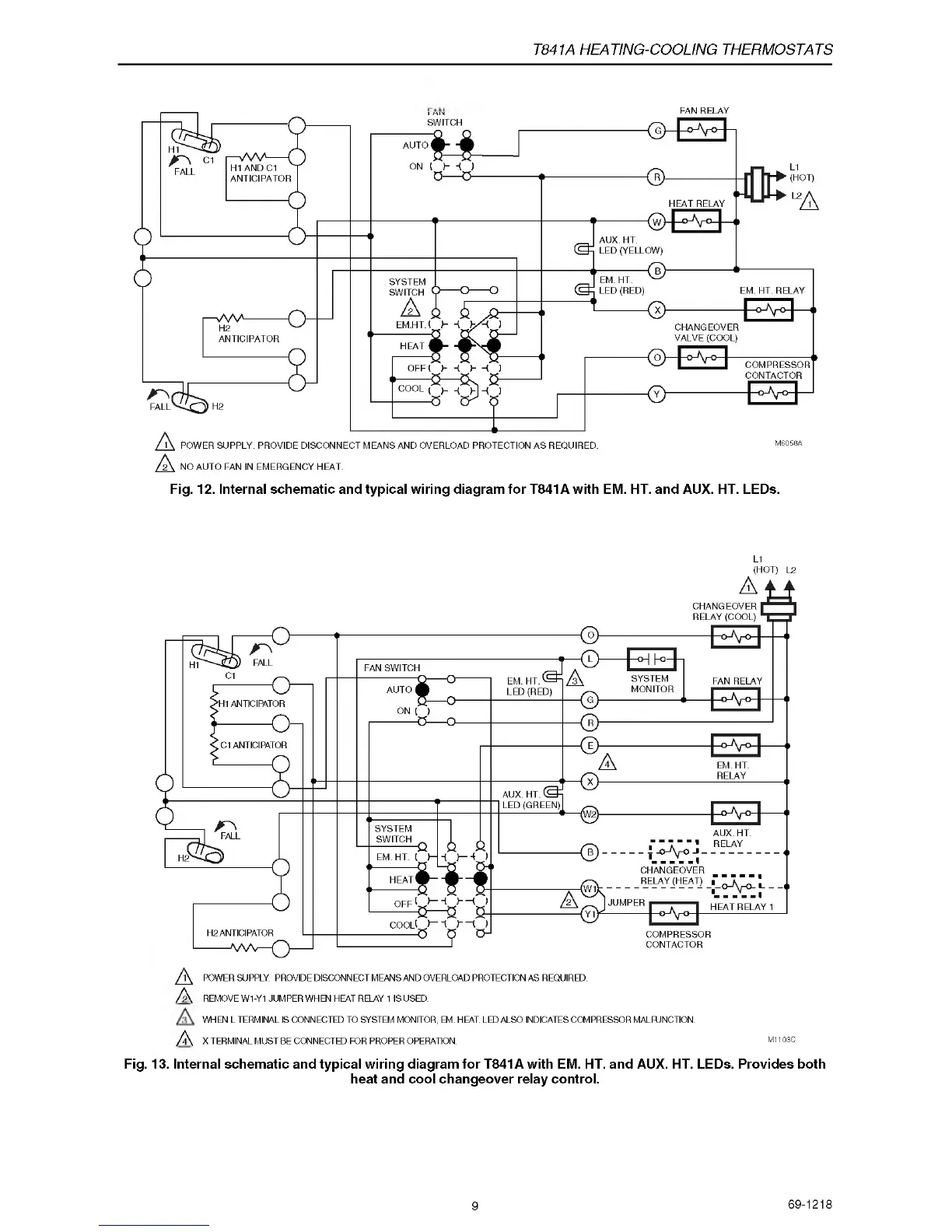
T841A HEATING-COOLING THERMOSTATS
FAN REIAY
Fig. 12. Internal schematic and typical wiring diagram for T841A with EM. HT. and AUX. HT. LEDs.
L1
(HOT) L2
/ K REMOVE W1-Y1 JUMPER WHEN HEAT RELAY 1 IS USED.
WHEN L TERMINAL IS CONNECTED TO SYSTEM MONITOR, EM. HEAT. LED ALSO INDICATES COMPRESSOR MALFUNCTION.
/ \ X TERMINAL MUST BE CONNECTED FOR PROPER OPERATION. M1103C
Fig. 13. Internal schematic and typical wiring diagram for T841A with EM. HT. and AUX. HT. LEDs. Provides both
heat and cool changeover relay control.
9
69-1218
 Loading...