B>E>
T874R THERMOSTATS AND Q674L SUBBASES
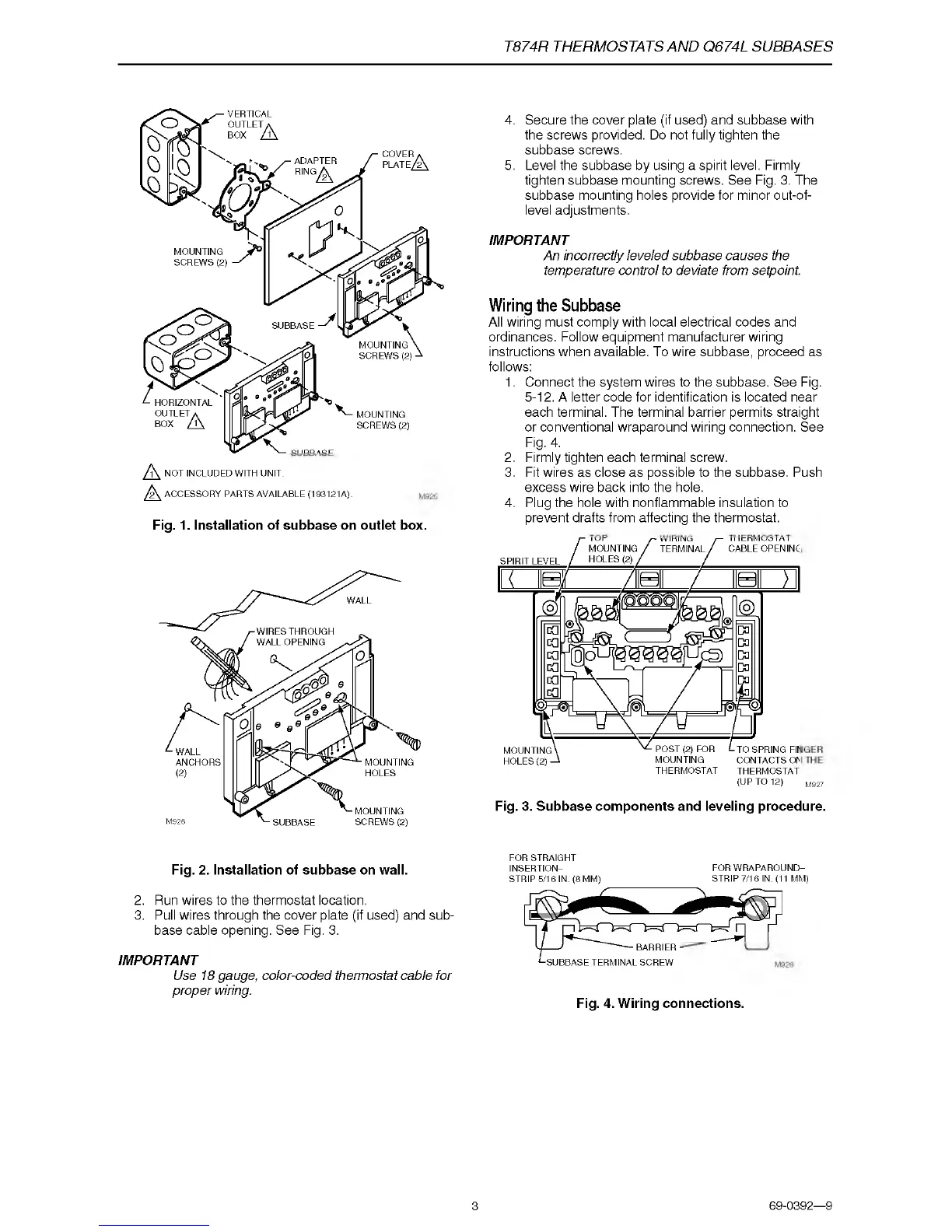
NOT INCLUDED WITH UNIT.
ACCESSORY PARTS AVAILABLE (193121A).
Fig. 1. Installation of subbase on outlet box.
4. Secure the cover plate (if used) and subbase with
the screws provided. Do not fully tighten the
subbase screws.
5. Level the subbase by using a spirit level. Firmly
tighten subbase mounting screws. See Fig. 3. The
subbase mounting holes provide for minor out-of
level adjustments.
IMPORTANT
An incorrectly leveled subbase causes the
temperature control to deviate from setpoint.
Wiring the Subbase
All wiring must comply with local electrical codes and
ordinances. Follow equipment manufacturer wiring
instructions when available. To wire subbase, proceed as
follows:
1. Connect the system wires to the subbase. See Fig.
5-12. A letter code for identification is located near
each terminal. The terminal barrier permits straight
or conventional wraparound wiring connection. See
Fig. 4.
2. Firmly tighten each terminal screw.
3. Fit wires as close as possible to the subbase. Push
excess wire back into the hole.
4. Plug the hole with nonflammable insulation to
prevent drafts from affecting the thermostat.
THERMOSTAT
THERMOSTAT
(U p TO 12) M927
Fig. 3. Subbase components and leveling procedure.
Fig. 2. Installation of subbase on wall.
2. Run wires to the thermostat location.
3. Pull wires through the cover plate (if used) and sub
base cable opening. See Fig. 3.
IMPORTANT
Use 18 gauge, color-coded thermostat cable for
proper wiring.
FOR STRAIGHT
INSERTION- FOR W RAPAROUND-
STRIP 5/16 IN. (8 MM) STRIP 7/16 IN. (11 MM)
-B A R RIER -
<-SUBBASE TERMINAL SCREW
Fig. 4. Wiring connections.
3
69-0392—9

 Loading...