4.7 mA Input Module Connections
This is an optional module for providing up to eight mA loop
inputs. (Ch.4.13)
Terminal Label Input Field Device
1 +Ve
mA input 1
+ 24 VDC
2 –Ve 0 VDC
3 Sig 4 – 20 mA signal
4 +Ve
mA input 2
+ 24 VDC
5 –Ve 0 VDC
6 Sig 4 – 20 mA signal
7 +Ve
mA input 3
+ 24 VDC
8 –Ve 0 VDC
9 Sig 4 – 20 mA signal
10 +Ve
mA input 4
+ 24 VDC
11 –Ve 0 VDC
12 Sig 4 – 20 mA signal
13 +Ve
mA input 5
+ 24 VDC
14 –Ve 0 VDC
15 Sig 4 – 20 mA signal
16 +Ve
mA input 6
+ 24 VDC
17 –Ve 0 VDC
18 Sig 4 – 20 mA signal
19 +Ve
mA input 7
+ 24 VDC
20 –Ve 0 VDC
21 Sig 4 – 20 mA signal
22 +Ve
mA input 8
+ 24 VDC
23 –Ve 0 VDC
24 Sig 4 – 20 mA signal
Table 3. mA Input Module Connections
4.8 mV Input Module Connections
This is an optional module for mV CAT sensor inputs. (Ch.4.13)
Terminal Label Input Field Device
1 S
mV input 1
Sensitive (+)
2 01 Signal
3 NS Sensitive (–)
4 S
mV input 2
Sensitive (+)
5 01 Signal
6 NS Sensitive (–)
7 S
mV input 3
Sensitive (+)
8 01 Signal
9 NS Sensitive (–)
10 S
mV input 4
Sensitive (+)
11 01 Signal
12 NS Sensitive (–)
13 S
mV input 5
Sensitive (+)
14 01 Signal
15 NS Sensitive (–)
16 S
mV input 6
Sensitive (+)
17 01 Signal
18 NS Sensitive (–)
19 S
mV input 7
Sensitive (+)
20 01 Signal
21 NS Sensitive (–)
22 S
mV input 8
Sensitive (+)
23 01 Signal
24 NS Sensitive (–)
Table 4. mV Input Module Connections
4.9 Dual Input Module
This is an optional module for providing 2 or 4 x mA Loop + 2
or 4 x mV CAT inputs.
Terminal Label Input Field Device
1, 7, 4, 10 +Ve
mA Inputs 1 – 4
+ 24 VDC
2, 5, 8, 11 –Ve 0 VDC
3, 6, 9, 12 Sig 4 – 20 mA signal
13, 16, 19, 22 S
mV Inputs 1 – 4
Sensitive (+)
14, 17, 20, 23 01 Signal
15, 18, 21, 24 NS Sensitive (–)
4.10 Modbus RTU Option
This is an option that uses Modbus RTU (RS-485) control
protocols. Full details are given in the Technical Handbook.
4.11 Relay Output Module Connections
This is an optional module providing 12 relay outputs.
(Ch.4.13)
Terminal Label Output
1 NC
Relay 1 2 COM
3 NO
4 NC
Relay 2 5 COM
6 NO
7 NC
Relay 3 8 COM
9 NO
10 NC
Relay 4 11 COM
12 NO
13 NC
Relay 5 14 COM
15 NO
16 NC
Relay 6
17 COM
18 NO
19 NC
Relay 7 20 COM
21 NO
22 NC
Relay 8 23 COM
24 NO
25 NC
Relay 9 26 COM
27 NO
28 NC
Relay 10 29 COM
30 NO
31 NC
Relay 11 32 COM
33 NO
34 NC
Relay 12 35 COM
36 NO
Table 5.
Table 6. Relay Output Module Connections
4.12 mA Output Module
This is an optional module for providing isolation mA loop
output (Ch.4.13).
Terminal Label Output
1 I+
mA Out 1
2 I–
3 I+
mA Out 2
4 I–
5 I+
mA Out 3
6 I–
7 I+
mA Out 4
8 I–
Table 7. mA Output Module Connections
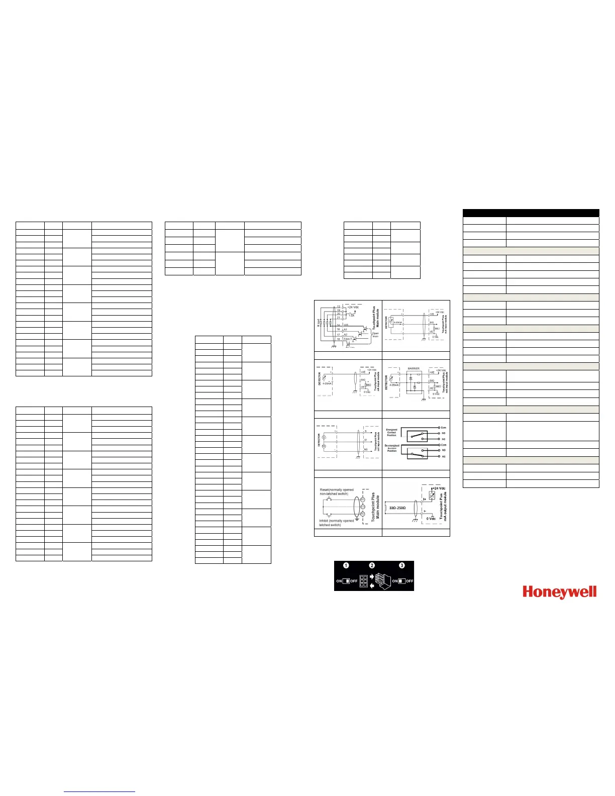
4.13 Field Device Circuit Diagrams
Figure 7. Dedicated Alarm Circuit Figure 8. Three Wire Devices
Figure 9. Two Wire Loop Devices Figure 10. Two Wire Barrier Devices
Figure 11. Catalytic Devices Figure 12. Relay Devices
Figure 13. Remote Switches Figure 14. mA Output Devices
4.14 Backup Battery Option
The optional backup battery is shipped in sleep mode. You
must read the manual before connecting it to the system.
Figure 15. Backup Battery Connection
5 Technical Specifications
General Specifications
Capacity Up to 8 inputs Base Unit, + 8 inputs with Expansion Unit
Type of Inputs 2 or 3 wires, mA, mV
Size (Wall Units only) 426 mm x 300 mm x 156 mm
Weight 9 Kg (20 lbs) Base Unit, 8.5 Kg (18.7 lb) Expansion Unit
User Interface
Display 7 inch Colour LCD Touch Screen GUI
Visual Indicators
3 LED Master Indicators and 16 LED inputs, Green for
Normal, Yellow for Fault/ Inhibit, and Red for Alarm
Audible Alarm 70 dB @ 1 metre (40 ins)
Button One alarm mute and reset membrane button
Languages
Selectable English, Chinese (Simplified), Dutch, French,
German, Italian, Portuguese, Russian, Spanish
Power Supply
Power AC
AC 110/220 V, 50 — 60 Hz
(Manual Voltage Selection via SMPS)
Power DC DC 18 — 32 V (24 VDC Nominal). DC 24 – 32 V advised
Power Consumption
105 W max (including field devices), 210 W max with
Expansion Unit
Environmental
Operating Temperature –10 to +55 °C (+14 to +131 °F) continuous operation
Storage Temperature Instrument –25 to +60 °C (–13 to +140 °F)
Humidity Range 5 – 95 %RH non-condensing
Ingress Protection IP65 (wall mounted), NEMA 4X indoors only
I/O Capacities
mV Input
Pellistor type Catalytic gas sensors (HA models).
2, 4, or 8 channels with Base Unit or 10, 12, or 16
channels with Expansion Unit
4 – 20 mA Input 2 or 3 wire, SOURCE. 2, 4, or 8 channel module
4 – 20 mA Output
4 or 8 repeated 0 – 22 mA outputs, 12 or 16 with
expansion unit. (4 – 20 mA = 0 – 100 %FSD)
Relay Output
Configurable time delay On/Off option. 1.7 A @ 250 VAC,
1.7 A @ 30 VDC, 12 relays per module
Certifications
Electrical Safety
Compliant with CE, EN 50270:2015, UL/
IEC/EN 61010-1, UL 508
Performance
ATEX, EN 60079-29-1 (pending)
EN 50104 (pending), EN 45544 (pending)
SIL 2 (pending)
CSA 22.2 no.152
CCCF, China – GB16808-2008 (pending)
Marine MED (pending)
Hazardous Approval
ISA 12.12.01–2013 (Class 1, Div 2, Groups A,B,C,D & T4)
CSA C22.2 No. 213–M1987
Others
Backup Batteries
22.2 V Lithium Ion, 2600 mAh.
Circa 30 mins Buffer time when fully charged.
Data Logging
Configuration backups and event / TWA logging onto SD
Card. Can be transferred to PC or Printer (.bin and .csv)
Communication Modbus RTU & TCP, Web Monitoring
6 Default Password
The default access password for all levels is TPPL, but it is the
User’s responsibility to immediately change the passwords as
to avoid unauthorized access. Full instructions are contained in
the Technical Handbook, and Honeywell will not accept any
liability caused by failing to follow these instructions.
Find out more:
www.honeywellanalytics.com
Please Note:
While every effort has been made to ensure accuracy in this publication, no responsibility can be accepted for
errors or omissions. Data may change, as well as legislation and you are strongly advised to obtain copies of the
most recently issued regulations, standards and guidelines. This publication is not intended to form the basis of a
contract.
Part No. 3011M5000_EN
H_MAN0985_HAA160009
Iss.2.0_02/2016
© 2016 Honeywell Analytics
 Loading...


