2 3 4 5
Automation and Control Solutions
Honeywell International Inc.
1985 Douglas Drive North
Golden Valley, MN 55422
Honeywell Limited-Honeywell Limitée
35 Dynamic Drive
Toronto, Ontario M1V 4Z9
http://yourhome.honeywell.com
Printed in U.S.A. on recycled
paper containing at least 10%
post-consumer paper fibers.
® U.S. Registered Trademark
© 2007 Honeywell International Inc.
All Rights Reserved
69-2144—01 M.S. 12-07
SOLENOID VALVE REPLACEMENT
CAUTION: Ensure outside of tank is cool before
removing to prevent possible injury.
Ensure the TrueSTEAM is empty, and unplug.
Shut off and disconnect the water line from the bottom
of the unit.
Unlock the red lever and disengage the tank from the
valve assembly and remove tank.
Remove TrueSTEAM from the mounting bracket.
Remove the cover with a athead or Torx screwdriver.
Disconnect the valve wire plug from the circuit board.
Using a athead screwdriver, disengage the frame’s
backplate at the four locations.
Slide the valve out of the back of the frame, and ease
the wiring out of the TrueSTEAM frame.
Reassemble with the new solenoid valve, following
steps 2–8 in reverse order.
IN-LINE WATER FILTER
Turn off water supply at the source (i.e. saddle valve)
Push in on the lter’s compression snap-lock ttings
where the 1/4-in. water line connects.
Pull out the water line as you are pushing in the snap-
locks.
Install the new water lter, ensuring directional water
ow is accurate per the lter label, by inserting the
water lines on either end of the lter.
Initiate a call for humidity by turning the humidistat on.
Check the lter after 5 minutes of humidier operation
to ensure no water leakage.
SEDIMENT SCREEN
Press and hold the EMPTY button for 3 seconds.
Water will drain from the tank and the CLEAN TANK
light will blink as it drains.
When the CLEAN TANK is on solid, the tank is empty.
Turn the water valve arm to the UNLOCK position.
Grip the solenoid toggle valve and slide it back to
disengage.
Hold bottom of the tank while pressing down the safety
release button on the cover and slide the handle
forward.
The sediment screen is on the inside of the tank at the
bottom. Push the release button away from the tank
wall to disengage the screen.
Pull out and clean or replace the screen.
1.
2.
3.
4.
5.
6.
7.
8.
9.
1.
2.
3.
4.
5.
6.
1.
2.
3.
4.
5.
6.
7.
WATER SENSOR ASSEMBLY
Unplug the TrueSTEAM.
Remove the cover with a athead or Torx screwdriver.
Disconnect the water sensor wire from the electric
circuit board.
Remove the Torx screw holding down the water sensor
assembly.
Lift the metal hinge and remove the sensor assembly
, .
Replace with the new sensor assembly and connect
the new wires to the assembly and the circuit board.
Reattach the cover.
Plug in the TrueSTEAM.
1.
2.
3.
4.
5.
6.
7.
8.
TROUBLESHOOTING
TrueSTEAM has internal diagnostics that monitor system
operation, maintenance schedules, and faults. If a system
fault is detected, the system will attempt to recover itself up to
ve times in a 24 hour period. If unable to recover in that time,
the red Call Service LED light will activate.
If the TrueSTEAM Call Service light is red, a system fault has
occurred from which the humidier can not recover by itself.
The table below shows the possible faults, along with steps to
x TrueSTEAM.
If the red Call Service LED light is on, press/release the
RESET button. The red Call Service LED light will begin
blinking in a series that indicates what fault occurred. Refer to
the table below for the fault signied by the number of blinks
that occur.
Press/hold the RESET button to clear the Service Timer light.
Press and hold the EMPTY button for 3 seconds to drain the
tank.
REPLACEMENT PARTS
Part Part Number Fig.
Reference
10-foot Remote Hose and
Nozzle Kit
50024917-001 1
20-foot Remote Hose and
Nozzle Kit
50024917-002 1
Cover 50028004-001 2
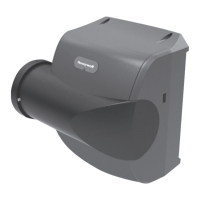
Duct Injection Nozzle for
Humidier
50028003-001 3
Remote Duct Nozzles 50028001-001 4
Mounting Bracket 50020012-001 6
Solenoid Valve 50027997-001 7
In-Line Water Filter 50028044-001 8
Sediment Screen for
Tank
50024895-001 9
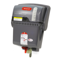
HM512/HM509 Water
Tank
50020017-001 10
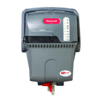
HM506 Water Tank 50025892-001 11
Water Level Sensor
Assembly
50027998-001 12
Wire Channel Harness 50022641-001 13
Latch 50024921-001 14
Saddle Valve 32001616-001 15
Air Pressure Switch IS30132-5972 -
TROUBLESHOOTING
No. of
Red
Light
Blinks
Fault
Description
Steps to Fix
To be Performed by Professional
HVAC Technician Only
1 Water/Heat-
er tempera-
ture sensor
failed.
• Unplug TrueSTEAM and remove
cover.
• Check water sensor connection
to electronic board.
• Reattach cover and plug
TrueSTEAM in.
• If fault reappears, press and hold
the EMPTY button for 3 seconds
and follow tank cleaning steps
in the Professional Installation
Guide (69-2036).
• Reassemble tank and press the
RESET button.
• If fault returns, replace the unit.
2 Water
sensors
failed.
• Unplug TrueSTEAM and remove
cover.
•
Disconnect water level
sensor wiring, remove screw and
lift clamp.
Remove water sensor
assembly.
• Clean sensor probes using warm
soapy water so that the metal
is exposed. It is OK to use steel
wool or brush.
• Reassemble the sensor
assembly in the unit, reattach
and secure cover.
• Plug unit back in and press the
RESET button.
• If fault reappears, replace sensor
assembly.
A
B
REPLACEMENT PARTS
A
B
Continued on other side…
 Loading...