Do you have a question about the Honeywell U2 and is the answer not in the manual?
Details grounding and shielding requirements for safe and reliable installation of the U2.
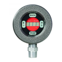
Explains wiring procedures for U2 models with pipe fittings and removable connectors.
Explains how IR and UV sensors operate and how their signals are processed.
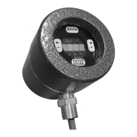
Details the touch wheel, LED indicators, and display for U2 operator interface and configuration.
Addresses '9999' display, lockout, and 'Bad' messages for troubleshooting.
Provides step-by-step instructions for configuring the U2 for gas firing applications with multiple burners.
Describes the normal open state and behavior of the flame relay under various conditions.
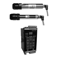
The Honeywell U2 Combination Viewing Head and Signal Processors is a FM-approved combustion safeguard and flame sensing system designed for various industrial applications. It combines multiple sensors and processing capabilities into a single unit, offering flexibility and advanced flame detection.
The U2 system integrates several flame-sensing technologies, including UV tube, solid-state UV (SSUV), and IR sensors, allowing it to adapt to different fuel types and combustion conditions. The primary function is to detect the presence or absence of a flame and provide a signal to a burner management system, ensuring safe operation.
The UV tube sensor is primarily used for gas and light oil flames, detecting radiation in the 210 nm range. The SSUV photodiode also detects UV radiation at 310 nm and is suitable for gas, oil, and coal. The IR photodiode detects radiation at 1,500 nm and is ideal for heavy oil and coal burners, as well as low NOx gas burners. The system can be configured to use one or a combination of these sensors depending on the specific application and fuel type.
The U2 features a Flame Relay that energizes when a flame-on condition is detected for a specified time delay and de-energizes when a flame-off condition is detected after the Flame Failure Response Time (FFRT) has elapsed, or if a fault condition is detected. This relay is crucial for safety interlocks within the burner management system. A Self Check Relay is also integrated, designed to energize during normal operation and de-energize upon fault detection or power down, enhancing safety by preventing false flame-on conditions due to welded relay contacts. Both relays are driven by an alternating signal to prevent faults from continuous high or low signals.
The system includes a user interface with a touch wheel for programming and configuration. This interface allows users to adjust various parameters such as sensor gain, filter settings, flame on/off thresholds, FFRT, and time delays. It also provides diagnostic information, including processor temperature, software version, and total run time. The U2 can store up to eight different configuration files, allowing for quick adaptation to different operating conditions or fuel types. These files can be selected via a 0/24 Vdc input or through a Modbus RTU interface.
Communication with a master control system is facilitated through Modbus RTU, enabling remote monitoring and control. The system supports various baud rates and parity settings for flexible integration into existing control networks.
The U2 is designed for ease of installation and configuration, though it requires a trained and experienced flame safeguard service technician. It can be mounted directly to the burner front or via a sight pipe, with various swivel mounts available to optimize the viewing angle. Proper sighting is critical to ensure reliable flame detection, especially in complex combustion environments with multiple burners or varying load conditions. The system can be aimed at the "root" or most intense spot of the flame to maximize signal strength and discrimination.
For applications with high temperatures or electrical isolation requirements, the use of insulating locking coupler adapters and purge air lines is recommended. A continuous flow of clean, cool purge air helps protect the U2 lens from dirt and debris and reduces conducted heat, maintaining optimal operating temperatures.
The U2 offers both manual and automatic setup options. Manual configuration involves adjusting sensor gains, filter settings, and flame thresholds based on specific fuel types (gas, oil, or coal) and burner conditions. This process often includes discrimination tests to ensure the U2 can reliably distinguish the target flame from background radiation or adjacent flames. For single burner systems, an automatic setup routine simplifies the configuration process by automatically adjusting sensor gains and filter settings.
The system's ability to store multiple configuration files is particularly useful for applications with different fuel types or operating modes. Users can switch between these files to optimize flame detection for varying conditions, such as during warm-up with natural gas and then switching to sour gas or oil. This flexibility helps maintain consistent and reliable flame detection across a wide range of operational scenarios.
The touch wheel interface allows for intuitive navigation through menus and adjustment of parameters. It provides feedback on current settings and diagnostic information, aiding in troubleshooting and optimization. The interface also includes features like panel lock and timeout settings to prevent unauthorized changes.
The U2 is designed for robust operation, but regular maintenance is essential to ensure its longevity and reliability. The UV tube sensor has a limited lifespan, which can vary from 10,000 to 50,000 hours depending on operating conditions. A monthly sensitivity check is recommended to determine if the UV tube sensor's sensitivity has degraded below 50% of its initial value, indicating the need for replacement. This check involves comparing the current digital display reading to the initial reading taken during installation, under similar burner fire conditions and gain settings.
The system also includes a proof test procedure that must be conducted every 1 to 5 years. This test verifies the proper functioning of the safety-related system, including the Flame Relay and Self Check Relay. The procedure involves checking continuity of relay contacts, generating flame-on and flame-off conditions with a light source, measuring current draw, and verifying that stored settings remain unchanged after power cycles. These steps ensure that the U2 continues to meet its safety integrity requirements.
The U2's internal temperature monitoring feature helps identify potential overheating issues, which could impact performance and lifespan. The system records the highest internal temperature achieved and the time it occurred, providing valuable diagnostic data.
For cleaning, it is important to note that the aluminum surface of the U2 may store electrostatic charge. Cleaning of painted surfaces should only be done with a damp cloth to prevent ignition in low humidity environments.
The modular design of the U2, with its various accessories like swivel mounts and purge air couplers, facilitates easier servicing and replacement of components if needed. The ability to remove the U2 for servicing is an important consideration during installation to ensure accessibility.
Overall, the Honeywell U2 system is engineered to provide reliable and flexible flame detection, with features that support both efficient operation and critical safety functions through its advanced sensing capabilities, user-friendly interface, and comprehensive maintenance guidelines.
| Input Voltage Range | 10-30 VDC |
|---|---|
| Output Signal | 4-20 mA |
| Protection Rating | IP67 |
| Operating Temperature Range | -40 to 85°C |
| Accuracy | ±0.1% of span |