USER MANUAL
66-2069-01
Honeywell Model 700/800 Signal
Processor and Viewing Head
APPLICATION
The Honeywell Model 700ACSP and Model 700DCSP signal
processors are single-channel, fail safe, flame monitoring
systems when used In conjunction with the S70X/S80X
viewing heads. They offer easy setup, excellent discrimination,
and high reliability.
FEATURES
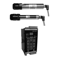
Viewing heads are interchangeable between the two signal
processor models. Any viewing head in the two families will
work with any of the signal processors.
Two signal processor models are available:
• Model 700ACSP Universal 85-265 VAC powered
• Model 700DCSP 22-26VDC powered
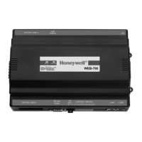
The two Model 700 signal processors are similar, with 12
push-buttons, a two-digit numeric display, and four LED status
indicators for operator interface. The only difference between
the two is that one accepts AC power and the other accepts
DC power. Both models also accept 24VDC backup power.
Most of the signal processor connections are made through
Phoenix plug-in connectors. Communication connections are
made through modular phone jacks located at the top of the
signal processors (Fig. 7).
Both signal processor models mount on a standard 35 mm
DIN rail. They snap into place and may be released from the
rail using a flat screwdriver.
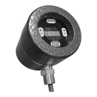
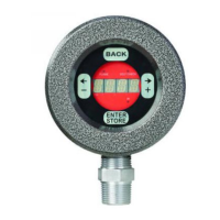
There are two types of viewing heads—IR/flicker-sensitive and
UV-sensitive—with various features offered resulting in ten
different models. See Table 1 on page 2 for details.
The S702 and S706 viewing head housings are larger in
diameter than the S80X series, are made of aluminum, and
are secured with over-center latches to their mounting blocks
(Fig. 8). In contrast, the S802 and S806 viewing head
housings are smaller in diameter and are made of stainless
steel (Fig. 9). An 800 series viewing head is secured in its
mounting block by a friction twist-lock.
The IR/flicker sensitive viewing heads have a high-pass filter
that passes flicker frequencies above 33 Hz. Some models
have a built-in high pass filter that only passes frequencies
above 155 Hz. The high frequency filter models are identified
by adding “HF” to the model number. The UV models respond
to the absolute level of UV radiation—not UV flicker—so there
is no filter option.
Contents
Application ....................................................................... 1
Features ........................................................................... 1
Specifications ................................................................... 3
Approvals ......................................................................... 3
Installation ........................................................................ 3
Operation ......................................................................... 11
Modbus Communication .................................................. 16
Troubleshooting ................................................................ 19
Maintenance .................................................................... 19
Safety Manual: 700 Signal Processor .............................. 35
Safety Manual: 70X & 80X Viewing Head ........................ 38