INSTALLATION INSTRUCTIONS
® U.S. Registered Trademark
Copyright © 2022 Honeywell Inc. • All Rights Reserved
31-00475-01
Spyder
TM
Model 7
VAV CONTROLLER
General ............................................................................... 3
Trademark Information .................................................... 3
Product Description........................................................... 3
Controller Part Numbers ................................................. 3
Dimensions ........................................................................... 4
Network Security ............................................................. 4
General Safety Instructions.......................................... 4
Specifications................................................................... 5
Electrical ................................................................................ 5
Operational Environment................................................ 5
Hardware................................................................................ 5
Integrated Actuator..............................................................5
Communications ................................................................ 6
Modbus Client...................................................................... 6
Sylk™ Supported Devices................................................. 6
Differential Pressure Sensor .......................................... 6
Weight And Dimensions .................................................. 6
Universal IO........................................................................... 7
Solid State Relay (SSR)..................................................... 7
Wireless Connectivity........................................................ 7
Hardware overview ......................................................... 8
IP Model ................................................................................. 8
MSTP Model ......................................................................... 8
Service Button...................................................................... 9
Mounting ........................................................................... 9
Before Mounting Actuator .............................................. 9
Mounting Actuator onto Damper Shaft................... 10
Airflow Sensor Connection ........................................... 12
Differential Pressure Installation
Recommendations........................................................... 12
Airflow Sensor Replacement........................................ 13
Power supply.................................................................. 14
General Information ........................................................ 14
Power Wiring....................................................................... 14
Power Wiring Examples.................................................. 15
Input / Output Wiring ................................................. 16
Wiring Requirements ...................................................... 16
Internal Wiring Examples.............................................. 17
Terminal Connections..................................................... 18
UIO Wiring Examples ...................................................... 19
SSR (DO) Wiring Examples........................................... 20
20 VDC Auxiliary Wiring Examples............................ 20
Network Concepts........................................................ 21
The RS-485 Standard..................................................... 21
TIA/EIA 485 Cable Specifications .................................. 21
IP Network Topologies.................................................... 21
Daisy Chain......................................................................... 21
Ring Topology.................................................................... 21
BACnet IP Controller ................................................... 22
DHCP IP Configuration.................................................. 22
Link-local addressing..................................................... 22
Static IP Configuration .................................................. 22
Connect to a IP Network................................................ 22
WiFi (Future Release) .................................................. 22
Install the Local Antenna.............................................. 22
Install the Remote Antenna ......................................... 22
Remote Antenna Placement........................................ 23
BACnet MSTP Wiring................................................... 24
Termination Resistors .................................................... 24
RS-485 Bias Switches .................................................... 24
BACnet MSTP Wiring Example ................................... 24
BACnet MSTP Controller ............................................ 25
Automatic MAC Addressing ......................................... 25
Manual configuration of the MAC Address ........... 25
Configure the Device Instance Number.................. 26
Connect to the BACnet MSTP Network ................... 26
Modbus RTU................................................................... 27
Modbus Considerations................................................ 27
Default Modbus values................................................ 27
Cables and Shielding...................................................... 27
Modbus RS-485 Repeaters.......................................... 27
Wiring Topology ................................................................ 27
Sylk™ Bus ........................................................................ 28
Supported Sylk bus devices......................................... 28
Sylk bus Wiring Example............................................... 28
Bluetooth Balancing.................................................... 29
Overview .............................................................................. 29
Troubleshooting............................................................ 30
BACnet and Modbus LED Status............................... 30
Bluetooth LED Status..................................................... 31
Controller LED Status .................................................... 31
Regulatory Information .............................................. 32
FCC Regulation................................................................. 32
Canadian Regulatory Statement ............................... 32
Professional Installation Warning.................................. 32
Detachable Antenna Warning (IC) ................................. 32
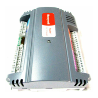
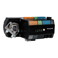
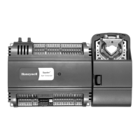

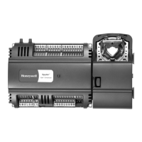



 Loading...