SPYDER MODEL 7 VAV CONTROLLER INSTALLATION INSTRUCTIONS
9 31-00475-01
Service Button
Fig. 5 Service Button Location
The service button is used to trigger dedicated events. It
is important to distinguish different controller
behaviors which are elicited depending upon whether
the service button is pressed when the controller is
powering up or when it is in normal operation.
See the following dedicated events:
Pressing Service Button during Power-Up
The controller is reset to factory settings when you press
the service button and turn it on (while the service
button is pressed). The factory defaults are as follows:
• The application is cleared from the controller.
• The MAC address will be set to 0xFF (255), meaning
that the controller will now search for a new MAC
address (Auto MAC will be automatically triggered
after controller power-up).
• The Max Master setting will revert to its default value.
See Automatic MAC Addressing on page 25 for the
default values.
• The max info frames will revert to 10.
• The device instance will revert to its default of
4194302.
• The device name will revert to WEB-VAxxxx.
• The values of Auto MAC, Min MAC, and Max MAC will
be reset to default.
• The Modbus, Ethernet, and Bluetooth settings will
revert to their factory settings. The user settings for
Modbus and BLE will be erased, the IP address will be
reset to default, and the device will enter DHCP IP
configuration.
Pressing Service Button during normal operation
During normal operation of the controller, a short press
(< 1 sec) of the service button will cause a service button
message (BACnet WhoAmI as a Private Transfer
(SerialNo. = 130)) to be sent.
Refer to the Spyder Model 5 and Spyder Model 7 System
Engineering Guide - 31-00282 for more information.
MOUNTING
To mount the Spyder Model 7 VAV, refer to the mounting
instructions provided with the controller. Before
mounting the controller on the damper shaft, review the
power, inputs and output specifications. See
Specifications on page 5.
Field devices driven by the analog current outputs must
have a maximum resistance of 550 Ohms. The resistor
must be installed on the field device.
NOTE:
Avoid mounting in areas where acid fumes or
other corrosive vapors can harm the metal parts
of the controller or in areas where escaping gas or
other explosive vapors are present.
Before Mounting Actuator
Spyder Model 7 VAV controller includes a direct-
coupled actuator with the declutch mechanism,
shipped hard-wired to the controller.
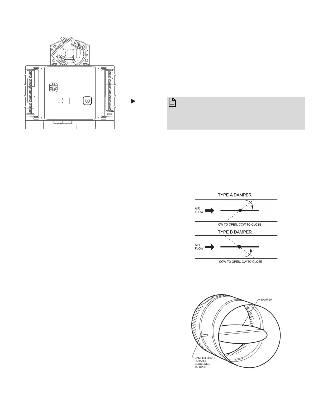
1. Determine the direction in which the damper shaft
rotates to open the damper. Typically, there is an
etched line on the end of the damper shaft that
indicates the position of the damper.
Fig. 6 Determining the Rotation Direction (CW or
CCW)
Fig. 7 Damper with 90 Degree CW Rotation to Open

 Loading...


