EasyManua.ls Logo

Honeywell S4565 User Manual

Honeywell S4565
66 pages
To Next Page IconTo Next Page
Page #1 background imageLoading...
Page #1 background image
PRODUCTION HANDBOOK
1 EN2R-9031 0402R15-NE
Subject to change without notice. All rights reserved
S4565, S4575 AND S4585
IGNITION CONTROLS FOR COMBINED VALVE AND IGNITION SYSTEM
APPLICATION
The Combined Valve and Ignition (CVI) system has been
developed for application in gas fired domestic central
heating boilers, combi boilers and warm air furnaces or water
heater appliances with an automatic ignition system.
For this system, the S4565, S4575 and S4585 ignition
controls are used in conjunction with the VK41.. series gas
controls to provide and optimised safety sub-system for
programmed safe light up and flame supervision of the main
burner of the appliance
The combined system then provides programmed safe light
up, flame supervision and regulation of gas flow to the main
burner and/or pilot burner of the appliance.
NOTE: The Combined Valve and Ignition (CVI) product concept consists of a specially designed gas valve family in
combination with a dedicated ignition controls family. This product handbook describes the CVI ignition controls family
S4565, S4575 and S4585 for use in combination with the CVI gas control family VK41.. For details of the CVI gas
controls please refer to Product Handbook EN2R-9004. For an up-to-date copy please contact your nearest
Honeywell office. For glossary of terms, abbrevations and symbols see document EN2R-9039
Question and Answer IconNeed help?

Do you have a question about the Honeywell S4565 and is the answer not in the manual?

Honeywell S4565 Specifications

General IconGeneral
BrandHoneywell
ModelS4565
CategoryController
LanguageEnglish

Summary

PRODUCTION HANDBOOK

Application Overview

Describes the system's use in domestic appliances.

DESCRIPTION

Valves

Details the gas valve component of the CVI system.

Ignition Control Types

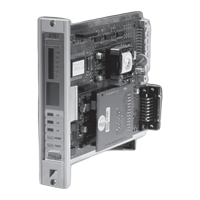
Explains S4565, S4575, and S4585 ignition controls.

FEATURES

General Features

Highlights overall system benefits and design.

Ignition Control Features

Lists specific functionalities of the ignition control.

Electrical Connection Options

Describes how electrical connections are made.

DIMENSIONAL DRAWING HOUSING

Housing Dimensions

Provides technical drawings of the standard housing.

DIMENSIONAL DRAWING "OLD STYLE" HOUSING

Old Style Housing Dimensions

Offers drawings for the previous housing design.

ACCESSORIES FOR DEGREE OF PROTECTION

IP Protection Accessories

Lists accessories for IP 20, 40, X4, 44 ratings.

ASSEMBLING OF IP X4/44 HOUSING

IP X4/44 Housing Assembly

Step-by-step guide for assembling IP X4/44 housing.

SPECIFICATIONS S4565A, B, P, Q

Technical Specifications

Details electrical, timing, and sensing parameters.

Warnings and Remarks

Important notes on operation and safety.

CONNECTION DIAGRAM S4565A, B, P, Q

Wiring Diagram

Illustrates the electrical connections for these models.

SYSTEM OPERATION S4565A, B, P, Q

Lock-out Reset and Sequence

Explains reset procedures and operational flow.

TIMING DIAGRAM S4565A, B, P, Q

Operational Timing

Visual representation of the control sequence timing.

SPECIFICATIONS S4565C, D, R, T

Technical Specifications

Details electrical, timing, and sensing parameters.

CONNECTION DIAGRAM S4565C, D, R, T

Wiring Diagram

Illustrates the electrical connections for these models.

SYSTEM OPERATION S4565C, D, R, T

Lock-out Reset and Operation

Explains reset and functional behavior.

TIMING DIAGRAM S4565C, D, R, T

Operational Timing

Visual representation of control sequence timing.

SPECIFICATIONS S4565AD, BD, CD, DD, PD, QD, RD, TD "1000" SERIES

Technical Specifications

Details parameters for the 1000 series.

CONNECTION DIAGRAM S4565AD, BD, CD, DD, PD, QD, RD, TD "1000" SERIES

Wiring Diagrams

Illustrates connections for the 1000 series.

SYSTEM OPERATION S4565AD, BD, CD, DD, PD, QD, RD, TD "1000" SERIES

Operational Sequences

Explains system behavior for the 1000 series.

SPECIFICATIONS S4565AD, BD, CD, DD, PD, QD, RD, SD, TD "2000" SERIES

Technical Specifications

Details parameters for the 2000 series.

SYSTEM OPERATION S4565AD, BD, CD, DD, PD, QD, RD, SD, TD "2000" SERIES

Operational Sequences

Explains system behavior for the 2000 series.

SPECIFICATIONS S4565AF, BF, CF, DF, PF, QF, RF, TF

Technical Specifications

Details parameters for these suffixes.

SYSTEM OPERATION S4565AF, BF, CF, DF, PF, QF, RF, TF

Operational Sequences

Explains system behavior for these suffixes.

APPLICATION NOTE S4565BF WITH SECOND MAIN VALVE CONTROL

Second Main Valve Control

Specific application for S4565BF.

APPLICATION NOTE S4565DF, TF WITH EXTERNAL MAIN BURNER INTERRUPT

External Main Burner Interrupt

Details interrupt function for S4565DF/TF.

SPECIFICATIONS S4565PV, QV, RV, TV

Technical Specifications

Details parameters for PV, QV, RV, TV models.

CONNECTION DIAGRAM S4565PV, QV, RV, TV

Wiring Diagrams

Illustrates connections for these models.

SYSTEM OPERATION S4565PV, QV, RV, TV

Operational Sequences

Explains system behavior for these models.

STATUS OUTPUT APPLICATION

Using Status Output

Guidance on reading and using status data.

SPECIFICATIONS S4575A, B, P, Q

Technical Specifications

Details parameters for S4575 models.

CONNECTION DIAGRAM S4575A, B, P, Q

Wiring Diagrams

Illustrates connections for S4575 models.

SYSTEM OPERATION S4575A, B, P, Q

Operational Sequences

Explains system behavior for S4575 models.

SPECIFICATIONS S4585D

Technical Specifications

Details parameters for S4585D.

CONNECTION DIAGRAM S4585D

Wiring Diagrams

Illustrates connections for S4585D.

SYSTEM OPERATION S4585D

Operational Sequences

Explains system behavior for S4585D.

TIMING DIAGRAM S4585D

Operational Timing

Visual representation of S4585D control sequence.

GENERAL CONSIDERATIONS

Installation and Operation Advice

Important tips for reliable operation.

EMC GUIDELINES

Emission Control

Guidelines for reducing radio frequency interference.

ELECTRICAL CONNECTIONS AND WIRING

Installation and Wiring Precautions

Essential safety and connection guidelines.

Flame Current and Sensing

Details on checking flame current and wiring.

STANDARDS AND APPROVALS

Compliance and Certifications

Lists European and North American standards.

ORDERING INFORMATION

Model Number Chart

Guide to specifying correct model numbers.

OVERVIEW IGNITION CONTROLS

Model Summary Table

Comprehensive table of ignition control models.

Related product manuals