EasyManua.ls Logo

Honeywell S9240F2051 User Manual

Honeywell S9240F2051
32 pages
To Next Page IconTo Next Page
Page #1 background imageLoading...
Page #1 background image
INSTALLATION INSTRUCTIONS
69-2807-01
S9240F2051 Modulating Integrated
Furnace Control
APPLICATION
The S9240F2051 Integrated Furnace Control (IFC) is
designed specifically to work with an Allied variable firing rate,
high efficiency furnace. It provides gas ignition, safety shutoff,
and variable speed fan control with multi-firing rate gas
heating and up to 2-stage electric cooling applications.
The S9240F2051 IFC is designed to work with:
A Conventional thermostat (one or two stages) with or
without a non-communicating outdoor unit (heat pump or
A/C).
An Allied communicating thermostat and non-
communicating outdoor unit (one or two stages).
An Allied communicating thermostat and communicating
outdoor unit (one stage, multistage, or modulating).
NOTE: When configured in a communicating system,
the IFC is able to communicate alarms, demands
for heat/cool/dehumidification/etc., and other
information to other components in the system.
Refer to the documentation for complete details
including operating mode sequences.
FEATURES
The S9240F2051 provides the following features:
Monitors a single stage or 2-stage conventional low
voltage thermostat for requests for heat, cool, or fan.
Monitors an input provided for connection to a
thermostat with a dehumidification output.
Provides three stage furnace input rate control when
operating with a conventional single stage thermostat.
Provides 2-stage or modulating furnace input rate
control based on field selected option when operating
with a conventional 2-stage thermostat.
Provides full modulating rate (between 40% and 100%
of furnace input) in response to an Allied
communicating thermostat.
Manages ignition of a main burner flame up to 400,000
BTU per hour using a 120 Vac hot surface igniter.
Monitors the appliance pressure, limit, and rollout
switches and generate control actions as programmed.
Controls the 24 Vac Honeywell amplified gas/air gas
valve.
Controls a 3-phase 120 Vac inducer motor (Fasco
Model 92B1 or other with identical voltage/frequency
curve) and blower assembly based on heat demand
and other parameters.
Controls the Regal Beloit or Nidec ECM circulator
motor and blower based on defined appliance CFM
profiles
and/or a discharge air sensor signal.
Controls single stage or 2-stage cooling equipment.
The outdoor unit is controlled directly by the 24 Vac
conventional thermostat inputs. The IFC manages the
circulator speed based on cool demand and other
parameters.
Controls a 120 Vac humidifier output and a 120 Vac
EAC output. Optionally, controls a 24 Vac low voltage
humidifier.
Operates with 120 Vac single phase, 60 Hz power
supply.
Uses a 7-segment LED display to communicate error
code and status information. A single on board button
is provided to generate the desired information
display.
Field selectable DIP switches to select field specific
control operating parameters such as type of
thermostat, delay timings, and fan operating
parameters.
On-board jumpers that can be clipped to permanently
enable 2-stage cooling, heat pump compatibility,
dehumidification sequences, and define appliance
characteristics for field replacement purposes.
Field Test Mode and Diagnostic Recall Mode to assist
the installation/service technician.
Stores the 10 most recent error codes, which are
accessible by the service technician in Diagnostic
Recall Mode.
Communications mode using an Allied communicating
thermostat.
On-board relays (Y1 and Y2) to control a 2-stage
compressor when using the communications mode
with an Allied communicating thermostat.
Question and Answer IconNeed help?

Do you have a question about the Honeywell S9240F2051 and is the answer not in the manual?

Honeywell S9240F2051 Specifications

General IconGeneral
BrandHoneywell
ModelS9240F2051
CategoryController
LanguageEnglish

Summary

APPLICATION

FEATURES

INSTALLATION INSTRUCTIONS

SPECIFICATIONS

Electrical Ratings

Electrical input/output parameters for the furnace control.

Timings

Specific time delays for various operational sequences and functions.

LED

Description of the 7-segment LED for system status and error codes.

Operating

Operating and storage temperature, and humidity limits.

Approvals

Safety and industry certifications for the control.

Location and Mounting

Wiring

Low Voltage Wiring Connections

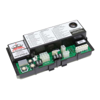
Terminal connections for low voltage thermostat and sensor inputs.

SETTINGS AND ADJUSTMENTS

Jumpers

On-board jumpers for enabling/disabling features like 2-stage cooling or heat pump.

DIP Switches

DIP switch blocks for configuring cooling, heating airflow, and sequences.

DIP Switch S1 Settings

Configuration options for DIP Switch S1 related to stage selection and delays.

CHECKOUT

Operation with Allied Communications

Information for systems configured with an Allied communicating thermostat.

Check Normal Operation

Procedures for checking normal heating and cooling operation sequences.

Pressure Switch Calibration

System calibration sequence required for initial startup and optimal performance.

Light Off

Normal Heat Mode - Conventional 2-Stage Thermostat

Call for Stage 1 Heat

Sequence for a 1st stage heat call in a 2-stage conventional system.

Call for Stage 2 Heat

Sequence for a 2nd stage heat call in a 2-stage conventional system.

Modulating Mode - Conventional 2-Stage Thermostat

Normal Heat Mode - Conventional Single Stage Thermostat

Call for Heat

Sequence for a call for heat in a single-stage conventional system.

Cooling Mode

Single Stage Cooling

Describes single-stage cooling operation sequence.

Two Stage Cooling

Describes two-stage cooling operation sequence.

Fan Mode

Call for Compressor Heat

Ignition Retry

Ignition Recycle

Rollout Circuit Operation

Limit Switch Circuit Operation

Low Pressure Switch Operation

High Pressure Switch Operation

Hot Surface Igniter (HSI) Control

Humidity Control

Electronic Air Cleaner

Error Conditions

Main Valve Sensing

IFC monitoring and actions for main valve sensing errors.

Flame Out of Sequence

Line Voltage Sensing

Weak Flame Sensing

Hot Surface Igniter (HSI) Sensing

Resets From Lockout

Indoor Blower Motor Failure

Inducer Motor Failure

Check Safety Shutoff Operation

TROUBLESHOOTING

LED User Interface

Explanation of the 7-segment LED display for status and errors.

Pushbutton

Using the pushbutton to access Idle, Diagnostic Recall, and Field Test modes.

LED Menu Options

Description of menu options accessible via the pushbutton.

Field Test Mode

System Status

LED Display Actions

Actions corresponding to LED display sequences for different modes.

SYSTEM STATUS LED DISPLAYS

Status Display Examples

Examples of LED displays for idle, errors, heating, CFM, and flame current.

LED Error Codes

Error Code Types and Handling

Categorization of error codes: Warning, Wait for Recovery, Soft Lockout, Hard Lockout.

Specific Error Codes (Table 12)

List of IFC error codes, their conditions, handling, and results.

Related product manuals