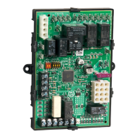
S9240F2051 MODULATING INTEGRATED FURNACE CONTROL
13 69-2807—01
Modulating Mode - Conventional
2-Stage Thermostat (special
modulating sequence selected)
The Allied modulating firing rate sequence and operation is
proprietary to Allied. Refer to the Allied documentation for
specific details.
Normal Heat Mode - Conventional
Single Stage Thermostat
Refer to Fig. 12 on page 21 for the operating sequence
diagram.
Call for Heat
A call for heat is signaled by the thermostat closing the
contacts between R and W1.
Upon a call for heat, the following occurs:
— After a successful Light Off and expiration of the
ignition stabilization period, the Inducer adjusts to the
low firing rate speed.
— After expiration of the heat fan on delay, the IFC
adjusts the circulator to the appropriate speed (CFM).
— If a discharge air sensor is present, the circulator
adjusts to maintain the target discharge air
temperature.
— The IFC remains in this state until the selected 2nd
stage on delay expires or the call for heat is removed.
When the 2nd stage on delay expires:
— The Inducer adjusts to the mid firing rate speed.
— The IFC adjusts the circulator to the appropriate speed
(CFM).
— If a discharge air sensor is present, the circulator
adjusts to maintain the target discharge air
temperature.
— The IFC remains in this state until the selected 3rd
stage on delay expires or the call for heat is removed.
When the 3rd stage on delay expires:
— The Inducer adjusts to the high firing rate speed.
— The IFC adjusts the circulator to the appropriate speed
(CFM).
— If a discharge air sensor is present, the circulator
adjusts to maintain the target discharge air
temperature.
— The IFC remains in this state until the call for heat is
removed.
Cooling Mode
Refer to Fig. 13 on page 22 for the operating sequence
diagram.
NOTES:
1. If a call for heat and a call for cool are present
simultaneously, the call for heat is serviced.
2. The circulator runs at the highest speed per the
thermostat request.
Single Stage Cooling
A call for cooling is signaled by:
— The shorting of R to Y1.
— The shorting of R to Y1 and G simultaneously.
Upon a call for cooling:
— The compressor and condenser fan energize directly
from the Y1 terminal pass-through signal from the
thermostat.
— The IFC does not directly control the compressor and
does not provide short cycle protection.
— The circulator energizes two seconds after the cool
request.
— The circulator starts according to one of the selectable
ramping profiles.
When the cool request is satisfied, the circulator de-energizes
per one of the selectable ramping profiles.
Two Stage Cooling
The two stage cooling jumper
a
on the IFC must be clipped to
enable two stage cooling control.
A call for 1st stage cooling is signaled by:
— The shorting of R to Y1.
— The shorting of R to Y1 and G simultaneously.
A call for 2nd stage cooling is signaled by:
— the shorting of R to Y2 while a valid call for first stage
cooling exists.
Upon a call for two stage cooling:
— The compressor and condenser fan energize directly
from the Y1 and Y2 terminals pass-through signal
from the thermostat.
— The IFC does not directly control the compressor and
does not provide short cycle protection.
— The circulator energizes at the low cooling speed two
seconds after the 1st stage cool request is detected
and switches to high cooling speed immediately after
the 2nd stage cool request is detected.
— The circulator starts and operates according to the
selected ramping profile.
— When the cool requests are satisfied, the circulator
de-energizes per the selected ramping profile.
Fan Mode
Refer to Fig. 14 on page 23 for the operating sequence
diagram.
— If the IFC is not currently servicing another circulator
request, the circulator energizes at the fan speed
when R is shorted to G and de-energizes when the
request is removed.
— If the IFC is servicing a fan request and a call for heat
or a call for cooling occurs, the circulator remains
energized at the continuous fan speed until it is
requested to move to the speed required by the heat
or cool demand.
Call for Compressor Heat
Removing the “O” jumper
b
indicates that the IFC is being used
in a heat pump system. The thermostat generates the “O”
signal. No signal on “O” with 24 Vac on Y1 or Y1+Y2 from the
thermostat indicates a call for compressor heat for stage 1 or
stage 2 respectively.
a
See jumper W915 in Table 4 on page 7.
b
See jumper W951 in Table 4 on page 7.

 Loading...
