Do you have a question about the Honeywell S9201A1010 and is the answer not in the manual?
Follow careful instructions, check ratings, ensure trained installer, and verify operation after installation.
Includes fire/explosion hazards from water exposure and LP gas, plus electrical shock and equipment damage cautions.
Mount control inside furnace wiring compartment with access, appropriate temperature/humidity, and protection.
Check diagrams, disconnect power, follow codes, ensure adequate transformer VA, and use correct wiring practices.
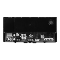
Details factory and field wiring connections for S9201 to various components like igniter, blower, and thermostat.
Illustrates typical wiring connections for the S9201 integrated furnace control with associated components.
Instructions for setting the heat anticipator in the thermostat based on gas control current draw.
Details on how to adjust the fan off delay time using switches, with a table of settings.
Steps to verify normal heating cycle operation by checking system sequence with thermostat calls.
Procedure to test safety shutoff by simulating flame failure and verifying lockout sequence.
Includes hazards, do not modify device, check manufacturer instructions, static discharge precautions, and repair limitations.
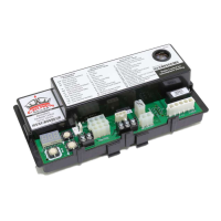
Explanation of PWR and OK status lights on the control for indicating input power and internal checks.
Step-by-step guide with checks for induced draft motor, igniter, gas control, and blower motor issues.
The Honeywell S9201A1010 Integrated Furnace Control is a device designed for use in high-efficiency gas-fired warm air furnaces equipped with an induced draft blower and a combination hot surface igniter/flame sensor. Its primary function is to manage the sequencing of ignition and burner operation, ensuring safe and efficient heating.
One of the key usage features of this control is its ability to handle multiple ignition attempts. If the initial lightoff is unsuccessful, the S9201 will attempt ignition up to five times before initiating a lockout. This feature enhances reliability by providing several chances for the furnace to ignite properly. Furthermore, the control is designed to return to ignition if an established flame fails during the run cycle, ensuring continuous heating operation when possible.
Beyond ignition, the S9201A1010 also manages the operation of various furnace components. It controls the indoor blower motor, offering both heating and cooling speeds to suit different comfort needs. The induced draft blower motor is also under its command, crucial for proper venting and combustion. Additionally, the control integrates with other home comfort systems, managing the operation of both the humidifier and the electronic air cleaner, contributing to overall indoor air quality and comfort.
For safety and proper operation, it's important to note certain usage limitations. The S9201A1010 cannot be used with a vent damper. It is specifically intended for residential furnaces, and any other applications require prior review and written approval from Honeywell Residential Design Engineering. This ensures that the control is used in environments for which it has been designed and tested, preventing potential hazards or malfunctions.
Maintenance and troubleshooting are facilitated by several features. The control includes two status lights: "PWR" and "OK." The "PWR" light illuminates whenever the control receives 24 Vac input power from the system transformer, indicating that the device is powered. The "OK" light signals that the control's internal checks are satisfactory. This light pulses at approximately six-second intervals during normal operation, confirming that the continuous self-check is functioning correctly. If the "OK" light goes out during operation, it indicates an internal issue, and the control must be replaced.
When troubleshooting, it's crucial to follow specific procedures. All meter readings should be taken within the trial for ignition period. Once this period ends, the system must be reset by setting the thermostat to its lowest setting and waiting at least 45 seconds before proceeding. This ensures accurate readings and prevents misdiagnosis. If any component is found not to be functioning properly, it's essential to verify its correct installation and wiring before considering replacement.
A critical maintenance consideration is the susceptibility of the integrated furnace control to static discharge. Static electricity can damage the device, so it's recommended to touch a metal surface to discharge any static electricity before handling the furnace control. This preventative measure helps protect the sensitive electronic components within the control.
The S9201A1010 is not designed to be repaired. If troubleshooting indicates a malfunction, the integrated furnace control must be replaced. This approach ensures that any faulty unit is swapped out for a new, fully functional one, maintaining the safety and reliability of the furnace system. Only trained and experienced service technicians should service these integrated furnace control systems, following the checkout steps and troubleshooting guide provided in the manual to ensure the system operates normally after any intervention.
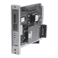
Installation guidelines emphasize proper placement and wiring. The control should be mounted inside the furnace wiring compartment in a location that allows access to field wiring terminals. The operating ambient temperature range is specified, along with requirements for relative humidity and protection from water, steam, corrosive chemicals, dripping water (e.g., from an overfilled humidifier), dust, and grease accumulation. A barrier between line and low voltage field wiring terminals is also necessary. The unit is designed for easy installation, snapping into predrilled holes on the mounting surface. Selecting a location close to the burner is recommended to allow a short, direct cable route to the igniter.
In summary, the Honeywell S9201A1010 Integrated Furnace Control is a comprehensive solution for managing residential gas furnaces, offering reliable ignition sequencing, blower motor control, and integration with other comfort systems, all while incorporating features for easy troubleshooting and emphasizing safety and proper installation practices.
| Ignition Type | Intermittent Pilot |
|---|---|
| Frequency | 60 Hz |
| Housing Material | Plastic |
| Trial for Ignition | 4 seconds |
| Ignition Source | Spark |
| Mounting | Panel |
| Weight | 1.5 lbs |