3 69-0685
• Any time work is done on the system.
The following procedures cover the integrated furnace
control only; see individual component instructions for addi-
tional checkout procedures.
Check Normal Operation
■ Turn on power to the appliance, and reset the furnace
control by turning the thermostat to its lowest setting and
waiting at least 45 seconds.
■ Set thermostat to call for heat. Make sure integrated
furnace control sequences the system as indicated in Table
3.
■ Set thermostat below room temperature to end call for
heat. Burner should go out, induced draft fan should stop and,
after delay time, indoor fan should stop.
TABLE 3—S9201A1010 SEQUENCE ON NORMAL
HEATING CYCLE.
SETTINGS AND ADJUSTMENTS
THERMOSTAT ANTICIPATOR
Set the heat anticipator in the thermostat to 0.1 plus the
current draw of the gas control.
FAN OFF TIMING
The fan off delay time is factory set at 90 seconds. To
change it, first disconnect power, then turn the switch screws
in or out according to Table 2. IN means to turn down until
snug; OUT means to turn out one to one and one-half full
turns.
TABLE 2—INDOOR FAN-OFF DELAY
TIME SETTINGS.
FAN OFF DELAY TIME SW 1 SW 2
60 sec. (factory setting) In In
75 sec. In Out
45 sec. Out In
90 sec. Out Out
CHECKOUT
Check out the control system:
• At initial installation of the appliance.
• As part of regular maintenance procedures.
• As the first step in troubleshooting.
Check Safety Shutoff Operation
■ Shut off gas supply at manual gas valve ahead of appli-
ance.
■ Set thermostat to call for heat. System should operate as
indicated in Table 4.
■ Following lockout, open manual gas valve and make sure
no gas is flowing to burner.
TABLE 4—S9201A1010 SEQUENCE ON FAILURE
TO LIGHT.
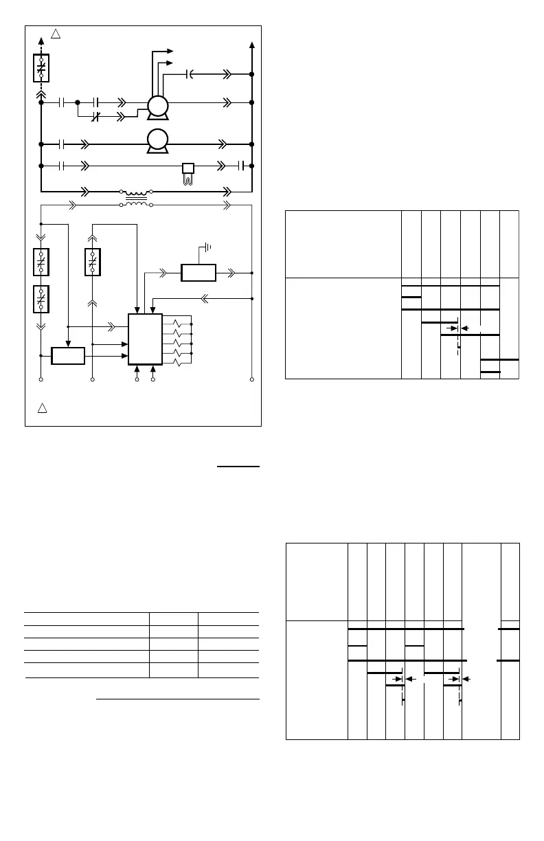
FIG. 2—LADDER DIAGRAM OF S9201 INTEGRATED
FURNACE CONTROL.
1 POWER SUPPLY. PROVIDE DISCONNECT MEANS AND
OVERLOAD PROTECTION AS REQUIRED.
L1 (HOT)
LIMITS
LIMIT
SENSOR
S9201
GAS
CONTROL
CGYWR
P1-8
P1-6
P1-3
P1-5
P1-2P1-4
P1-9
PRESSURE
SWITCH
3K
24 VAC
COM
COM
24 VAC
24 VAC
120 VAC
CONTROL TRANSFORMER
N
P2-3
IGNITER
INDUCED
DRAFT MOTOR
P2-6
L1
P2-1
P2-45K1
3K1
4K1
4K2
COOL
HEAT
M2
M1
RUN CAPACITOR
N
N
INDOOR
BLOWER
MOTOR
BLOWER
DOOR SWITCH
1
L2
M1433A
4K
5K
6K
7K
6K1
7K1
PREPURGE
(30 SECONDS)
IGNITER WARM UP
(36 SECONDS)
TRIAL FOR IGNITION
(9 SECONDS)
NORMAL RUN
PERIOD
FAN ON DELAY
(30 SECONDS)
FAN OFF DELAY
(90/45/60/75 SEC.)
THERMOSTAT CALL FOR HEAT
PREPURGE
INDUCED DRAFT BLOWER ON
IGNITER ON
GAS CONTROL OPEN
PROOF OF FLAME
INDOOR BLOWER MOTOR, EAC ON
HUMIDIFIER* ON
1 SEC.
* IF HUMIDIFIER CONTROLLER IS CALLING FOR HUMIDIFICATION.
M888
PREPURGE
(30 SECONDS)
IGNITER WARM UP
(36 SECONDS)
TRIAL FOR IGNITION
(9 SECONDS)
BETWEEN TRIAL PURGE
(30 SECONDS)
THERMOSTAT
1 SEC.
M889
IGNITER WARM UP
(36 SECONDS)
TRIAL FOR IGNITION
(9 SECONDS)
LOCKOUT (IMMEDIATE)
PURGE,
IGNITER
WARM UP,
IGNITION
SEQUENCE
REPEATS
3 MORE
TIMES
1 SEC.
CALL FOR HEAT
PREPURGE
INDUCED DRAFT
BLOWER ON
IGNITER ON
GAS CONTROL
OPEN
PROOF OF FLAME
INDOOR BLOWER
MOTOR, EAC ON
HUMIDIFIER
ON
 Loading...