INSTRUCTION SHEET
S4565/S4575/S4585 SERIES
IGNITION CONTROLS FOR COMBINED VALVE AND IGNITION SYSTEM
EN1R--9161 0006R10--NE
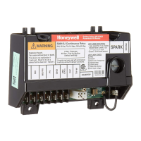
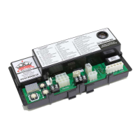
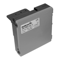
”Old”-- style
”New”-- style
APPLICATION
The Combined Valve and Ignition system (CVI) has specially
been developed for application in gas fired appliances with
either intermittent pilot or direct burner ignition.
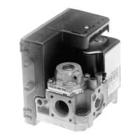
For this system, the VK41../VK81.. series gas controls have
been designed to have the S4565/S4575/S4585 series
ignition controls attached directly onto the valve.
The combined system then provides programmed safe light
up, flame s upervision and regulation of gas flow to the main
burner and/or pilot burner of the appliance.
DESCRIPTION
The S4565/S4575 ignition controls provide automatic ignition
for direct gas burner applications and for intermittent pilot gas
burner applications with safety timer.
The S4565/S4575 ignition controls are not intended for direct
exposure to flame envelope.
The S4585 ignition controls provide automatic ignition for
intermittent pilot gas burner applications without safety timer.
The S4565/S4575/S4585 ignition controls are designed to
meet the european standards:
EN 298: Automatic gas burner control systems.
EN 60730--1: Automatic electrical controls for house hold
and similar use.
The S4565/S4575/S4585 ignition controls can be used in
appliances according European standard for household
electrical requirements EN 60335 series.
The S4565/S4575 ignition controls are approved on the North
American standard ANS Z21.20 Automatic Ignition Systems.
NOTE: S4565SD is not an ignition control but an ignition
circuit and rectifier only
Contents
Page
Dimensional drawing 2................................
Features 3...........................................
S4565A,B,P,Q 3.......................................
S4565C,D,R,T 4.......................................
S4565AD,BD,CD,DD,PD,QD,RD,TD “1000” series 7......
S4565AD,BD,CD,DD,PD,QD,RD,SD,TD “2000” series 13..
S4565AF,BF,CF,DF,EF,PF,QF, RF, TF 18..................
S4575A,B,C,D,P,Q,R,T 23..............................
S4585D 26...........................................
General c onsiderations 27.............................
Electrical connections 28..............................
Subject to change without notice. Printed in the Netherlands.


 Loading...