Do you have a question about the Honeywell ESYS S4965A3025 and is the answer not in the manual?
Lists the standards (EN 298:2012, EN 55014-1, EN 60730-1) the ESYS controller meets and related electrical requirements.
Details the EC Directives (Gas Appliance, Low Voltage, EMC) the boiler control conforms to, including conformity statements.
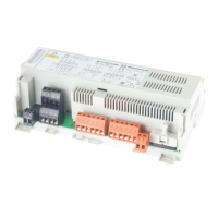
Provides a general overview of the S4965A3025 controller's intended use for ON/OFF applications and direct burner ignition.
Details the physical dimensions, PCB thickness, fixing points, and tolerances for the component side of the ESYS controller.
Covers the technical specifications including connector types, voltage connections, and communication interfaces.
Explains the Minifit and Microfit connectors for high voltage (230 VAC) and low voltage safety connections.
Lists the pin assignments and descriptions for high voltage (230 VAC) connections, spark ignition, and flame input.
Details the pin assignments and descriptions for the MicroCom communication connector, including UART settings.
Details the pin assignments and descriptions for low voltage (LV) connections, including switch inputs and outputs.
Outlines the nominal electrical specifications, power consumption, humidity, ambient temperature, and communication parameters.
Illustrates the timing sequence for ignition, safety time, flame extinguish, and alarm functions of the ESYS controller.
Recommends specific peripheral devices like atmospheric valves and displays for use with the ESYS controller.
Describes the sensors and actuators connected to the ESYS controller, including safety switches, LEDs, and gas valves.
Explains the function of the safety cut-off (high limit) switch in preventing overheat damage and its role in lockout conditions.
Details the use of the Alarm/Error LED output for remote fault indication to external systems.
Describes the low error output signal indicating lockout status to the second ESYS unit.
Specifies the type of gas valve (CVI-m) compatible with the ESYS controller and suggests contacting Honeywell for options.
Describes the Stand-by mode where the igniter and gas valve are off, typically when no heat demand or errors are present.
Explains how a Heat Demand input triggers the boiler to switch on, provided no errors are present.
Details the controller's checks for protecting the system, leading to error/fault or warning conditions, including lockout and blocking codes.
Outlines the ignition sequence process, including re-ignition attempts and the flame lockout error indication upon failure.
Provides general installation guidelines, including IP protection, environmental considerations, non-repairable parts, and fused protection.
Details the procedures for safe electrical connection, emphasizing power off, legislation adherence, and proper grounding.
Covers requirements for wiring, including cable length, insulation, routing separation for different voltages, and flame sensor protection.
Explains how to check the ionization current value and troubleshoot issues related to immersion and grounding.
Guides qualified persons through adjustments, flame current checks, and final appliance checkout procedures.
Provides guidelines for minimizing electromagnetic interference (EMI) and radio frequency interference (RFI) during installation.
| Manufacturer | Honeywell |
|---|---|
| Series | ESYS |
| Output Type | Relay |
| Housing Material | Plastic |
| Model | S4965A3025 |
| Controller Type | Electronic |




 Loading...