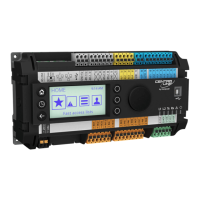
Do you have a question about the Honeywell Enraf and is the answer not in the manual?
Details electrical connections, field wiring, breakers, and enclosures for the prover.
Details the initial startup sequence and the Prover Status screen information displayed.
Explains how to navigate controller menus using the LAD, including the main menu and input fields.
Describes the screen for locking and unlocking the SVP Controller with a password for security.
Details accessing and modifying device configuration parameters via the Configuration menu.
Step-by-step guide for the safe removal and replacement of seals and initial prover operation.
Details the default operating mode for meter calibration and its status screen.
Explains how to use the Prover Test mode to verify prover operation and familiarize the user.
Procedure for performing static leak detection to ensure prover integrity before calibration.
Details the equipment and procedure for volumetric calibration using water draw.
Explains the equipment and procedure for gravimetric calibration using water draw.
Lists common error messages and their potential causes and solutions.
Describes diagnostic screens like Dashboard and System Health for troubleshooting.
Provides a table to help diagnose and resolve prover issues.
Presents electrical schematics and diagrams for prover wiring configurations.
Details how to connect the SVP Controller to various flow computers like Omni, Condat, Daniels, and Dynamic.
| Brand | Honeywell |
|---|---|
| Model | Enraf |
| Category | Controller |
| Language | English |


