Controller Information
2-12 SVP Controller Operation Manual Part No.: 44200004 - Revision 2
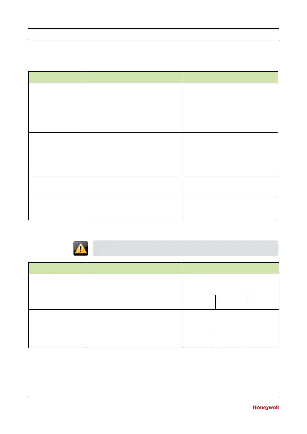
2.3.6.2.4 Time
Entity Description Value range
[Date display format] This entity selects the format of the date • DD-MM-YY
• MM-DD-YY
• YY-MM-DD
• DD-MM-YYYY
• MM-DD-YYYY
Note: Only the first 3 selections will be
completely visible on the SVP screen
[Time display format] This entity selects the format of the time • 24 hours
• 12 hours
Note: When setting the clock, first set the
controller to 24-hour mode, then set the time.
This will allow the proper AM or PM to be
displayed when 12-hour mode is selected.
[Date] This entity selects the actual date and will
be used for time stamping of transactions,
calibrations, and alarms
[Time] This entity selects the actual time and will
be used for time stamping of transactions,
calibrations, and alarms
2.3.6.2.5 Motor
These parameters are set at the factory and must not be changed without
consulting Honeywell Enraf experts or damage to the prover may occur.
Entity Description Value range
[Motor switch timeout] Configurable time interval by which piston puller
must have reached motor stop switch before
detection of a motor timeout error. Covers
retraction of piston from parked position to
motor stop switch. Units are in seconds
Configurable range is from 5 seconds to
120 seconds; factory recommended settings
per model are shown below.
S05 16 S35 38 S120 62
S15 14 S50 26
S25 22 S85 58
[Motor off delay] Configurable delay which controls when motor
turns off after piston puller has retracted to
motor stop switch. Can be adjusted to affect
optimal positioning of puller in preparation for
next retraction sequence. Units are in seconds
Configurable range is from 0 to 60 seconds;
factory recommended settings per model are
shown below.
S05 0 S35 2 S120 2
S15 0 S50 2
S25 1 S85 2
2.3.6.2.6 Sensor Pair
Standard provers have an Upstream optical sensor and a Downstream
optical sensor. An option is available for a third optical switch. The
configuration entities are as shown below.

 Loading...


