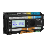
Do you have a question about the Honeywell Excel 100C and is the answer not in the manual?
Crucial safety guidelines for installation personnel and procedures.
Prerequisites for starting controller installation and system integration.
Guidance on installing and integrating associated peripheral equipment.
Step-by-step guide for opening and preparing the controller unit.
Procedures for mounting the controller within a control cabinet.
Explanation of status indicators provided by the controller's LEDs.
Comprehensive mapping of all controller input and output terminals.
Fundamental rules and compliance for making electrical connections.
Best practices for routing cables to minimize signal interference and ensure safety.
Guidelines for using and grounding shielded cables for sensors and actuators.
Requirements for shielding communication cables to prevent interference.
Procedures and considerations for establishing a proper system ground connection.
Techniques and components for suppressing radio frequency interference.
Specifications for maximum cable lengths and conductor cross-sections.
Instructions and requirements for connecting the controller to its power source.
Overview of supported communication methods and system architecture.
Specific terminal connections for various analog input signals.
Performance data detailing the accuracy of analog input sensors.
Configuration options for input signal pull-up resistors.
Specific terminal connections for various digital input signals.
Wiring details for connecting external relay modules.
Connections for peripheral control devices like relays and actuators.
Wiring instructions for utilizing alarm output relays.
Defines logical states for digital inputs and outputs based on contact position.
Details on the controller's serial communication bus protocol.
Recommended cable specifications for the C-Bus communication.
Methods to extend the length of the C-Bus network using repeaters.
Wiring procedures for connecting operator interface units.
Configuration of the serial port for communication device selection.
Physical connections for modems and ISDN adapters.
Essential specifications for compatible modem hardware.
Default modem configuration without special settings.
How communication speeds are automatically matched between devices.
System behavior for handling incoming communication calls.
Procedure to reset modem to factory default settings.
Advanced configuration steps for specific modem functionalities.
Configuration for modems connected to internal phone networks.
Critical safety warnings related to the M20T GSM terminal usage.
List of essential external hardware components for GSM communication.
Description of the RS232 serial cable for connecting the GSM terminal.
Electrical specifications for antennas used with GSM communication.
Guidance on proper placement and installation of GSM antennas.
Step-by-step configuration process for the M20T GSM terminal.
Diagrams and instructions for connecting sensors in US installations.
Types of sensors and transmitters compatible with US specifications.
Specifications for power transformers used in US systems.
Cable types and specifications for US system bus and connections.
Details on relay specifications and part numbers for US applications.
Specifications and ordering info for repeaters in US systems.
Diagrams and instructions for connecting sensors in European installations.
Types of sensors and transmitters compatible with European specifications.
Transformer specifications for European installations.
Relay specifications and part numbers for European applications.
Cable types and specifications for European system bus and connections.
| Brand | Honeywell |
|---|---|
| Model | Excel 100C |
| Category | Controller |
| Language | English |
