EXCEL 100C INSTALLATION INSTRUCTIONS
EN1R-0144GE51 R1007 36
Serial Cable
For connecting the M20T to the Excel controller, a standard RS232 cable (9-pin V24
sub-D sockets) is required.
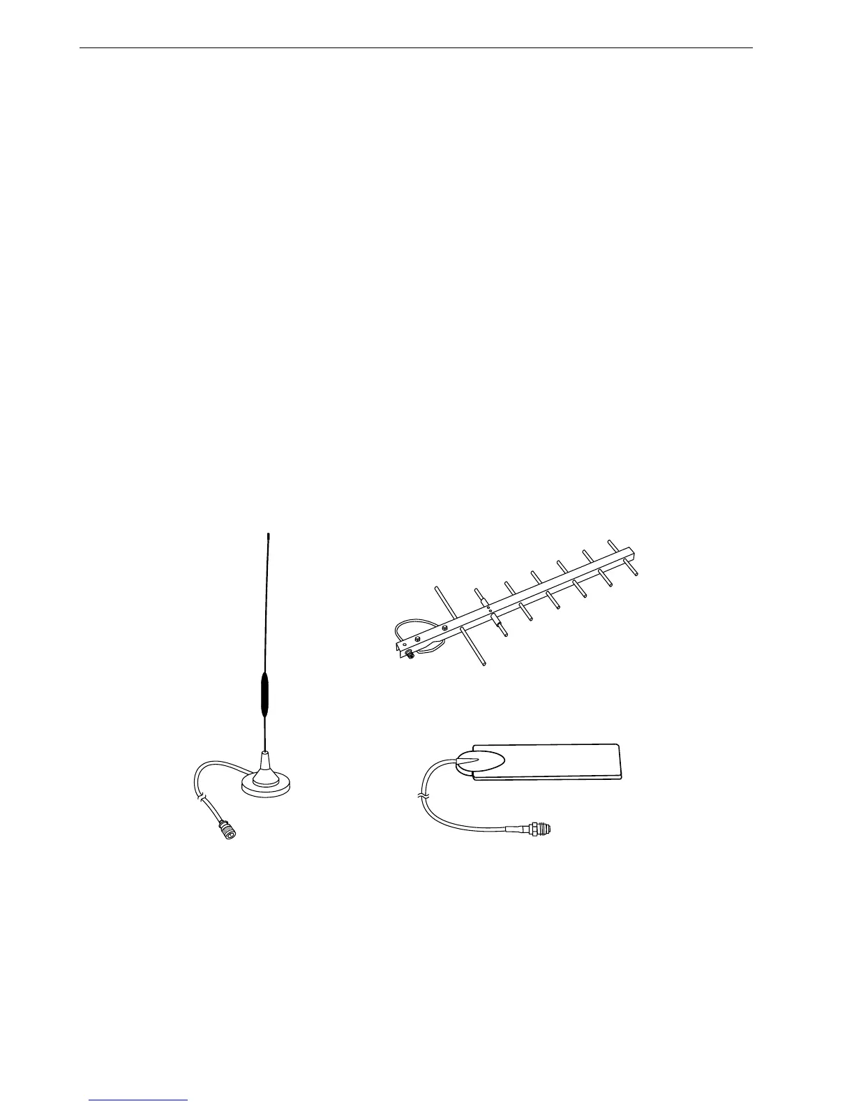
GSM Antenna Requirements
All major suppliers of GSM antennas can supply GSM900 Antennas with FME plugs
to connect with the M20 Terminal for a variety of applications. Some antenna
examples are shown below.
The antenna must satisfy the following electrical requirements:
Frequency TX 890-915 MHz
Frequency RX 935-960 MHz
Impedance 50 Ω
VSWR TX: max. 1.7:1 installed
VSWR RX max. 1.9:1 installed
Gain > 1.5 dB referenced to
λ
/2 dipole
3dB width of cone vertical: 80°; horizontal: 360°
Maximum power 1 W (cw), 2 W peak; at ambient temperature of 55°C
Depending on the application and the RF field at the local site, the GSM antenna
may be mounted directly or via cable. The maximum antenna cable length is 8.0 m
(including 20 cm M20 Terminal-cable)
NOTE:
The maximum number of push/pull cycles shall not exceed 100.
The antenna interface connector of the M20 unit is a FME connector (of type SMR
nano (male)). Hence, the connector on the GSM antenna or antenna cable has to
be of type SMR nano (female, or use a double female connector in between).
ROUND RADIATION ANTENNA,
MAGNETIC BASE, 5 dBi
WINDOW PATCH ANTENNA, 2 dB
DIRECTIONAL ANTENNA (YAGI), 12 DbI
 Loading...


