EXCEL 100C INSTALLATION INSTRUCTIONS
9 EN1R-0144GE51 R1007
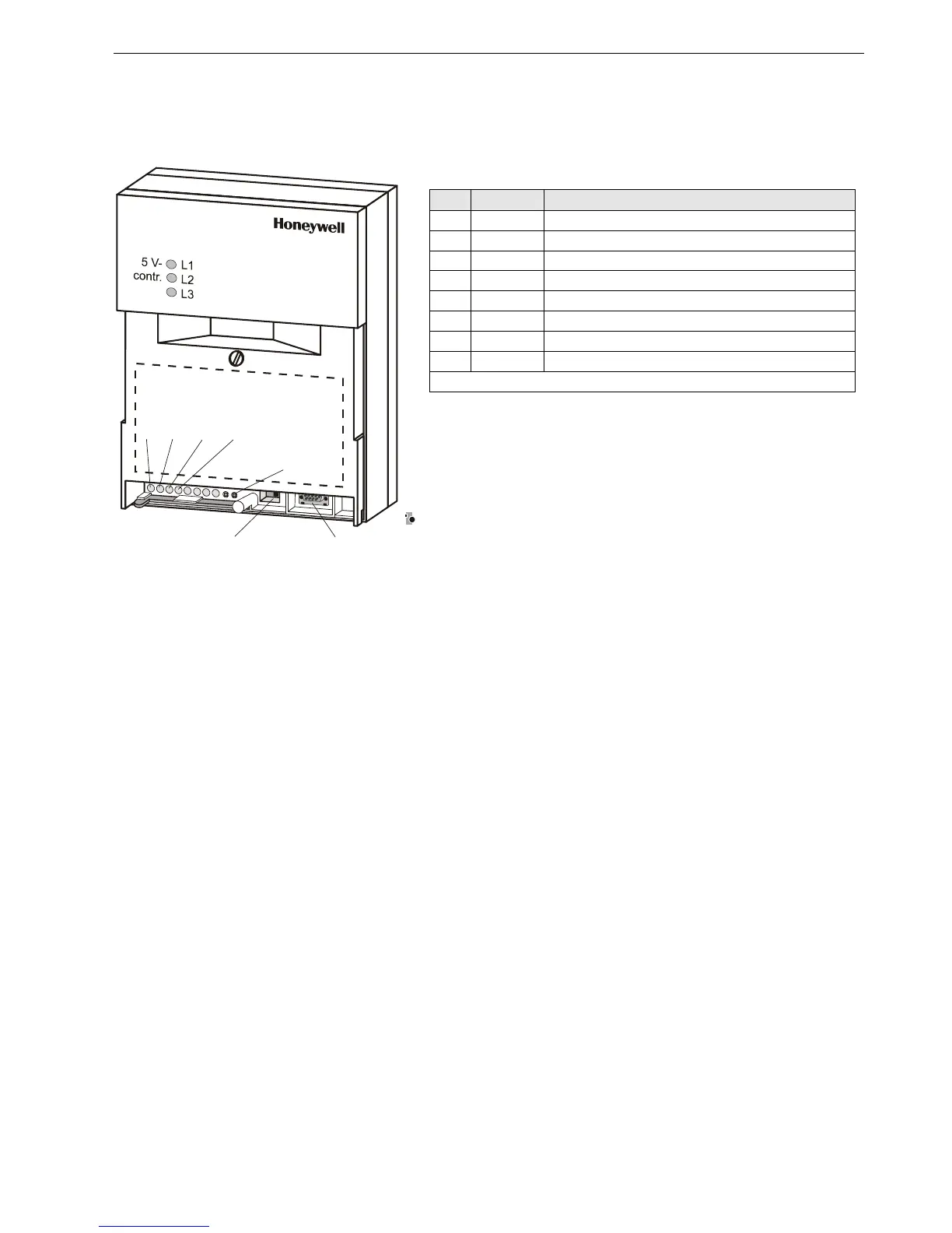
Meaning of Control Lamp
Table 1. Control Lamps and their meanings
LED color status/meaning
L1 YELLOW Lit: Main voltage is present
L2 GREEN Lit: Program is running
Dark: Program is stopped
L3 RED Lit continuously: ALARM; program is stopped
L4 YELLOW Lit : Controller is transmitting via B-port
L5 YELLOW Lit: Controller is receiving via B-port
L6 YELLOW Lit: Transmission via C-bus to system bus interface
L7 YELLOW Lit: Reception via C-bus from system bus interface
L8, L9, L10, and L11 are for future use
NOTE: L4 to L11 are visible only if the cover plate has been removed.
IMPORTANT
The RESET button reboots the controller’s CPU. All plant-
specific data held in the controller will be lost after a reboot.
Before rebooting, it is highly recommended that you save the
current application to the flash EPROM.
See section "Setting the Port Selector Switch" on page 30 for details on
setting the port selector switch and serial port.
CB-0603-E1
L4 L5 L6 L7
RESET
BUTTON
PORT
SELECTOR
SWITCH
FRONT
SERIAL
POR
 Loading...


