EXCEL 100C INSTALLATION INSTRUCTIONS
EN1R-0144GE51 R1007 22
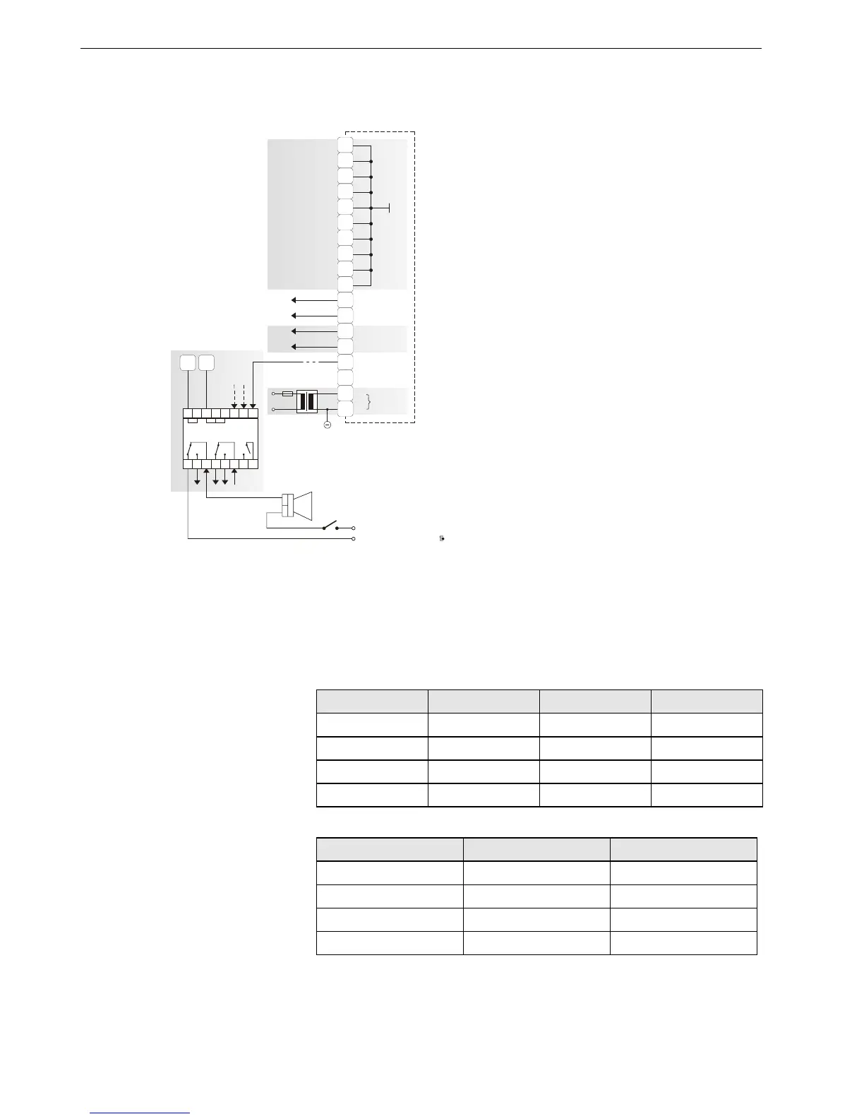
Connection of Alarm Relays
The selection of a signal transmitter for the
watchdog alarm is optional. It is recommended
that a switch for turning off the alarm be
provided.
NOTE:
Terminal 69 is used to control the module MCE
3, only. The digital output cannot be used for a
relay.
Normally Open/Normally Closed Attribute
Beginning with V2.04.00 firmware, the point attribute NO/NC defines the relation
between the physical states (contact position and relay ON/OFF, respectively) at the
digital inputs and outputs and their logical status; see also Table 8 and Table 9.
Table 8. Digital input parameters
contact position
NO/NC attribute logical status input voltage
open NO 0
≤
2.5 V
closed NO 1
≥
5 V
open NC 1
≤
2.5 V
closed NC 0
≥
5 V
Table 9. Digital output parameters
relay ON/OFF
NO/NC attribute logical status
ON NO 1
OFF NO 0
ON NC 0
OFF NC 1
−
+
55
56
57
58
59
60
61
62
63
64
65
66
67
68
69
70
71
72
COMMON
Watchdog
max. 240
V
/
2
A
External supply
24V~
+
66 65
11 12 13 14 15 16 17 18
12345678
MCE 3
K2
K3
K1
−
+
C
B
-
0
7
0
8
-
E
1
not used
 Loading...


