Do you have a question about the Honeywell Sieger System 57 and is the answer not in the manual?
Details System 57 gas control cards, their LCD displays, and input options.
Describes System 57 fire control cards, zone inputs, LEDs, and output circuits.
Explains the optional master alarm update panel for enhanced update facilities.
Details rack-mounted power supply units, capacity, and input/output features.
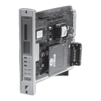
Describes the engineering card for maintenance, setup, and system options.
Lists interface card versions for connecting detectors to control cards.
Outlines rack assembly options for mounting control and interface cards.
Describes System 57 cabinets for mounting racks and PSUs.
Explains the DC input card for connecting power to the entire rack.
Details proper cable connection to system protective earth for safety.
Shows wiring for 5701 Gas Card and Catalytic Type Detector connections.
Explains 2-wire loop powered detector connections for 5701 Gas Card.
Details 3-wire 4-20mA transmitter connections for the 5701 Gas Card.
Illustrates 5704 Gas Card connections for Catalytic Type Detectors.
Shows 2-wire loop powered detector connections for 5704 Gas Card.
Details 3-wire 4-20mA transmitter connections for the 5704 Gas Card.
Describes the 5704F fire input circuit operation and voltage limiter.
Provides a guide to maximum cable lengths based on loop resistance.
Explains loop powered detector connections to the 5704F Control Card.
Details intrinsically safe detector connections with IS barriers.
Covers connections for separately powered detectors like IR, UV/IR Flame.
Explains connections for Manual Activated Call Points and switched output detectors.
Details connections for fire detectors with voltage-free alarm and fault contacts.
Lists standards the system is designed to comply with, including EN standards.
Specifies operating temperature, storage temperature, and humidity limits.
Details RFI/EMC conformity according to relevant directives and standards.
| Brand | Honeywell |
|---|---|
| Model | Sieger System 57 |
| Category | Controller |
| Language | English |