System 57 Quick Start Guide 05701-M-5026 MAN0839 Issue 1
should be connected to the GROUND terminal of the Hex Relay Interface Card or to a
suitable instrument earth point.
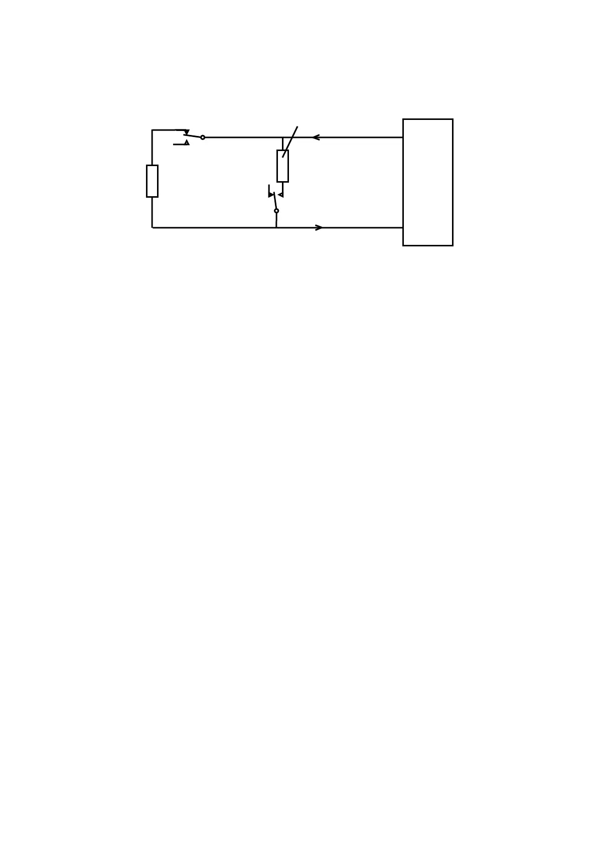
Notes: 1. Some detectors may incorporate the alarm current resistor shown with a typical
alue of 620 ohms, if not, this can be easily fitted externally within the detector junction box.
v
2. Where the detector is earthed locally, either to an earth stud or through the detector
casing or mounting, to avoid earth loops the screen sheath of the cable should be connected
at one end only.
Normally Closed
Fault Contact
Normally Open
larm Contact
620
EOL
5.1k
IN-
23
21
larm Current Resistor
IN+
Volt Free Output Detector
5704 Hex Card
The diagram shows the detector connections for Channel 1. Channel 2, 3 and 4 connec
rminal connection numbers are shown in section 7.
tions
are similar and their te
19
 Loading...