System 57 Quick Start Guide 05701-M-5026 MAN0839 Issue 1
8.8 5704 Fire Card
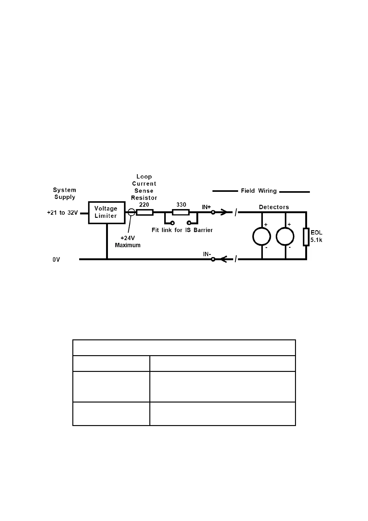
The 5704F fire input circuit operates from the system dc input supply (21 to 32V) but has a
built-in voltage limiter that limits the maximum loop voltage to +24V to protect the detectors
from damage. When the system supply is less than +24V the limiter has no effect and the
loop will see the true input supply voltage. The loop current is determined by measuring the
voltage across a 220 ohm current sense resistance. A link selectable 330 ohm barrier
equivalent resistance is incorporated for use when an external IS barrier is NOT fitted. For
fault monitoring purposes, an end of line (EOL) resistor must be fitted in or after the last
detector on the loop. The typical value for the end of line resistance is 5.1k ohms although
this may need to be reduced when many detectors are fitted onto the loop.
An equivalent circuit of one fire input together with an example detector connection is shown
below:-
8.8.1 Line Resistance
Detectors should be located such that the line resistance of the cable required does not
prevent correct operation. As a general guide and for a typical installation of twenty low
quiescent current detectors, the loop cable resistance should be kept below 100 ohms total
(50 ohms per core). The table below gives a quick guide to the maximum cable lengths
permitted in this case:
Maximum Cable Length (m)
Detectors Conductor Cross Sectional Area
AWG 21 19 18 16 14
mm
2
0.50 0.75 1.00 1.50 2.50
20 low quiescent
(100µA) detectors
1300 2000 2700 4100 6500
For further details of line resistance calculation refer to the 5704F Fire Card manual 05704-
M-5002.
14
 Loading...