System 57 Quick Start Guide 05701-M-5026 MAN0839 Issue 1
8 Detector Connections
The following sections show generic installation schematics for the most common types of
fire or gas detector and System 57.
8.1 Cable Earthing/Grounding
The detector cable screen or steel wire armour (or braid), as appropriate, should be
connected to the system (protective) earth. This can be achieved where the cable enters the
cabinet by using a metal cable gland, or by other suitable means, and avoiding any screen
'tails' within the cabinet.
Where the cable consists of a separate screen sheath and wire armour (or braid), the
armour should be connected, at the cabinet entry, to the protective earth and the screen
sheath should be connected to the GROUND terminal of the Field Interface/Relay Card or to
a suitable instrument earth point.
Note: Where a detector is earthed locally, either to the Earth Stud or through the detector
casing or mounting, to avoid earth loops the screen sheath of the cable should only be
connected at one end, i.e., at the detector or at the Interface/Relay Card.
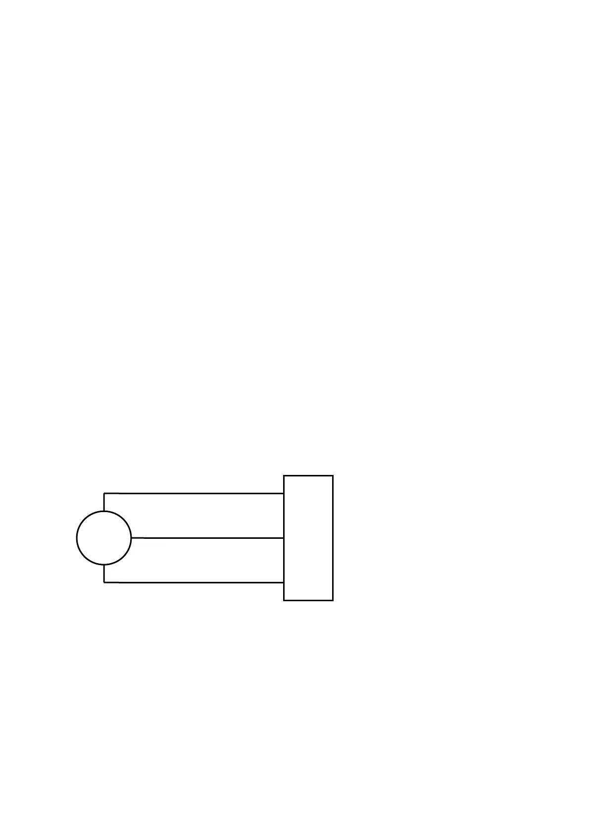
8.2 5701 Gas Card and Catalytic Type Detector
Catalytic detectors require a three wire connection and the detector documentation will
indicate three connections S, 01 and NS, which are usually brown, white and blue
respectively. At the System 57 end of the field cable, the three detector wires should each be
connected to the respective matching S, 01 or NS terminal on the Field Interface or Relay
Card that is attached to the required Single Channel Display Card.
NS
S
01
29
28
27
Detector
NS
S
01
5701 Interface Card
8.3 5701 Gas Card and 2 Wire Loop Powered Detectors
Loop powered detectors require a two wire connection and the detector documentation will
indicate the positive and negative loop connections, usually brown and blue respectively.
At the System 57 end of the field cable the two detector wires should each be connected to
one of either the S, 01 or NS terminals on the Field Interface or Relay Card that is attached
to the required Single Channel Display Card. The two terminals used will vary depending
upon whether the location of the measuring resistance is in the loop supply or return paths.
9
 Loading...


