Do you have a question about the Honeywell S9360A and is the answer not in the manual?
Details product application, model numbers, specifications, and 2012 DOE compliance.
Covers electrical ratings, flame monitoring parameters, and available accessories.
Includes transformer needs, product approvals, and environmental considerations for installation.
Provides guidance on mounting the module and connecting wiring according to safety standards.
Details connecting ignition cables, inducer, and gas control for proper operation.
Instructions for installing the temperature sensing bulb and immersion well.
Defines various state codes used by the integrated boiler control for operation.
Explains temperature control setpoints, adjusting settings, and display readout parameters.
Details the thermal purge function, its purpose, and conditions for burner release.
Steps to diagnose and correct issues with the spark ignition circuit and pilot flame.
Lists and defines error codes displayed by the integrated boiler control for fault diagnosis.
Provides examples and causes of unsatisfactory pilot flames, and troubleshooting steps.
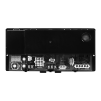
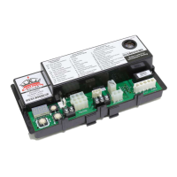
The Honeywell S9360A, S9361A, S9380A, and S9381A are integrated boiler controllers designed to manage the ignition sequence, flame monitoring, and safety shutoff for heating systems. These models support both intermittent pilot spark ignition and direct spark ignition. A key feature is their ability to provide limit-rated water temperature control, utilizing either one or two sensors. They also offer display interface capabilities, supporting both on-board and remote user interfaces, enhancing flexibility for various applications.
These integrated boiler control modules are central to the safe and efficient operation of gas-fired heating systems. They initiate the ignition sequence, ensuring the burner lights reliably. Once lit, they continuously monitor the flame to confirm its presence and stability. In the event of a flame failure or other unsafe condition, the controllers activate a safety shutoff to prevent the accumulation of unburnt gas, thereby mitigating fire or explosion hazards.
The temperature control function is critical for maintaining desired water temperatures within the boiler. The controllers use temperature sensors to monitor the boiler water and activate or deactivate the burner as needed. This ensures that the system operates within safe and efficient temperature ranges. The setpoint and differential for temperature control can be adjusted, allowing customization for specific heating requirements.
A notable feature is the "Thermal Purge Operation." This function is designed to circulate residual heat out of the boiler before the burner is allowed to fire again. On a call for heat, the burner is held off while the circulator runs until the boiler temperature drops to a predefined thermal purge temperature limit or a set time delay expires. This process helps to maximize energy efficiency by utilizing existing heat and prevents short cycling of the burner. The thermal purge parameters, including temperature limit and time delay, are adjustable. Additionally, the system will exit thermal purge if the boiler temperature drops significantly from its initial reading or if it cools at a rapid rate while the circulator is running, ensuring comfort is maintained.
The controllers are also enabled with EnviraCOM™ communication capability, which allows for remote monitoring and diagnostics. This feature is particularly useful for commercial or industrial applications where remote management and early detection of issues can prevent costly downtime.
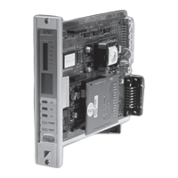
The S9360A, S9361A, S9380A, and S9381A models offer different display options. The S9360A and S9380A models require a remote display, while the S9361A and S9381A models feature an integrated on-board display. The on-board display, typically a three-digit 7-segment LED, facilitates adjustments and troubleshooting directly at the unit. Users can view status items and parameters such as boiler temperature, operating setpoint, high limit setpoint, differential setpoint, flame current, run time hours, boiler cycles, and error codes.
Adjusting settings on models with an on-board display involves a specific procedure to prevent unauthorized changes. Users must simultaneously press the UP, DOWN, and I buttons for three seconds to enter the adjustment mode. Once in this mode, the I button can be pressed to cycle through parameters, and the UP or DOWN buttons can be used to adjust values. The control automatically reverts to READ mode after 60 seconds of inactivity.
The controllers support various igniter sensor types, including two-rod (separate igniter and sensor) and one-rod (combined igniter and sensor) configurations, providing flexibility for different pilot assemblies. Ignition cables must adhere to specific length and insulation requirements to ensure proper operation and prevent spark voltage reduction.
These controllers incorporate advanced diagnostic capabilities, providing error codes to assist in troubleshooting. The display shows specific error codes (e.g., Err 2 for pressure switch failure, Err 4 for low flame current, Err 32 for sensor error) that help service technicians quickly identify the root cause of a problem. This reduces diagnostic time and simplifies repairs.
Regular preventive maintenance is emphasized, especially in severe environments such as commercial, agricultural, and industrial applications where equipment may experience frequent cycling, intermittent use, or exposure to harsh conditions (dust, wetness, corrosive chemicals, excessive heat). Monthly checkouts are recommended for systems with high cycling rates (over 10,000 cycles annually). Appliances used seasonally should be checked before and after use.
The manual provides detailed troubleshooting steps, including checks for the ignition cable, ignition system grounding, and pilot/main burner lightoff. It also offers guidance on identifying and correcting issues related to pilot flame appearance, such as small blue flame, lazy yellow flame, waving blue flame, noisy lifting/blowing flame, and hard sharp flame.
The controllers are designed as sealed units and cannot be repaired internally; if a module malfunctions, it must be replaced. It is crucial to protect the module from water, moisture, corrosive chemicals, excessive dust, and grease. In environments prone to these conditions, a NEMA 4 enclosure is recommended to extend the life of the control. Proper air circulation and insulation are also important to prevent damage from high ambient temperatures. Any control that does not perform properly during checkout or troubleshooting, or appears to have been wet, should be replaced.
| Voltage | 24 Vac |
|---|---|
| Frequency | 50/60 Hz |
| Output Voltage | 24 Vac |
| Power Supply | 24 Vac |
| Humidity Range | 95% RH non-condensing |
| Application | Industrial and commercial burners |
| Ignition Type | Direct spark ignition |
| Approvals | UL, CSA |
| Temperature Range | -40°C to 70°C (-40°F to 158°F) |
| Operating Temperature Range | -40°C to 70°C (-40°F to 158°F) |