S9360A, S9361A, S9380A, S9381A INTEGRATED BOILER CONTROLLERS
66-1203—05 12
Temperature Control
Temperature control setpoint on the module can be
adjusted as described in the following sections. Some
modules with temperature control also include a three-
digit display on the printed circuit board to facilitate
adjustments and troubleshooting.
For modules that do not include temperature control on
the module refer to the Honeywell Installation Instructions
for the specific interface module or the appliance
manufacturer’s instructions. A separate automatic gas
shutoff device is not required in a system that uses this
control to meet requirements for CSA International ANSI
Z21.87 and UL 353.
The overall range of the setpoint is model-dependent but
is within 130°F to 240°F (54°C to 116°C). Select devices
may have different ranges.
Adjusting Settings for Models with
“On-Board” Display
To discourage unauthorized changing of settings, a
procedure to enter the adjustment mode is required. To
enter the adjustment mode, press the UP, DOWN, and I
buttons (see Fig. 1) simultaneously for three seconds.
Press and release the I button until the parameter
requiring adjustment is displayed.
Then press the UP or DOWN button until the parameter
has reached the desired value. After 60 seconds without
any button inputs, the control will automatically return to
the READ mode.
Display
In the RUN mode, status items and parameters are
viewable.
To read settings, press and release the I key to find the
parameter of interest. For example, press and release I
until setpoint (sp) is displayed, followed by a three-digit
number, i.e., 220, followed by °F or °C. See Display
Readout, Fig. 7.
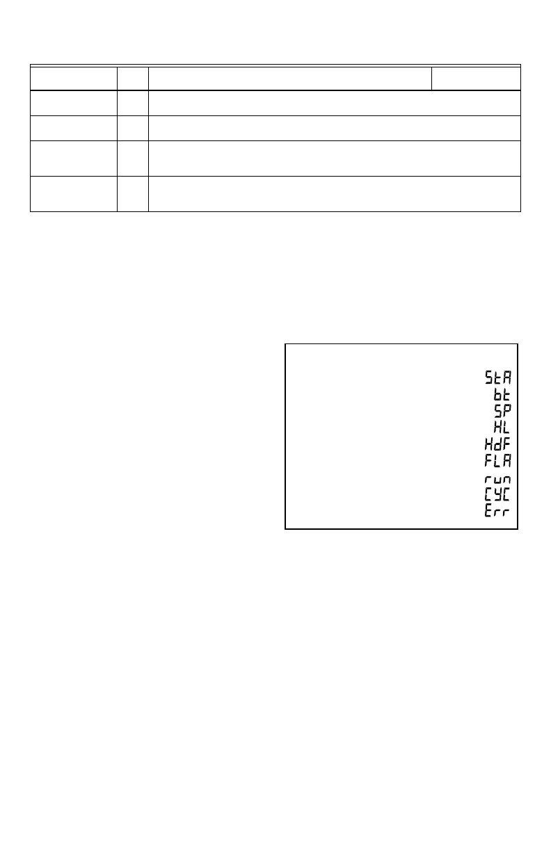
Fig. 7. Display readout parameters.
Wait for vent
damper to open
18 Damper actuator is energized and the system waits for damper to close
Wait for vent
damper to close
19 Damper actuator is de-energize and the system waits for damper to open
Wait for vent
damper to open –
failed closed
20 Damper actuator is energized, system waits for damper to open, but the damper is stuck
in closed position (damper end switch is open)
Wait for vent
damper to close –
failed open
21 Damper actuator is de-energized, system waits for damper to close, but the damper is
stuck in open position (damper end switch is closed)
Table 5. State Code Definitions. (Continued)
State
State
code Specific Description
General
Description
OPERATING SETPOINT
TEXT DESCRIPTION
DISPLAY
SHOWS
SP
STATUS (SEE STATUS NUMBERS)
BOILER TEMPERATURE
STA
BT
HIGH LIMIT SETPOINTHL
DIFFERENTIAL SETPOINTHDF
FLAME CURRENTFLA
RUN TIME HOURS RUN
ERROR (SEE ERROR NUMBERS)
ERR
M33683
BOILER CYCLES CYC
 Loading...