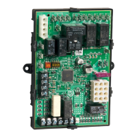
S9240F2051 MODULATING INTEGRATED FURNACE CONTROL
69-2807—01 14
These 24 Vac signals directly control a one or two stage heat
pump.
— No heat fan on delay is present for compressor heat.
— The circulator energizes without delay when
compressor low or high heat is requested.
— Compressor heat calls and fossil fuel calls can be
serviced simultaneously. The circulator energizes at
the speed requested by the compressor or fossil fuel
heat sequence, whichever is higher.
Ignition Retry
When flame is not sensed during the Trial for Ignition or is lost
less than 10 seconds after exiting Trial for Ignition:
— The gas valve is de-energized.
— The inducer remains energized at the ignition speed
and holds for the Interpurge Period.
— When the Interpurge Period expires, a new trial for
ignition is started again for up to a maximum of four
additional trials.
— After the fifth Trial for Ignition has failed to light the
burner the IFC proceeds to Soft Lockout where it
remains for the Auto Restart Delay before beginning
another set of ignition sequences.
— An error code flashes on the LCD.
— The retry count is cleared if flame is sensed for longer
than 10 seconds after exiting Trial for Ignition (low fire
operation).
Ignition Recycle
When flame is established during Trial for Ignition, maintained
for at least 10 seconds, and then lost:
— The gas valve is de-energized.
— The inducer remains energized at the ignition speed
and holds for the Interpurge Period.
— When the Interpurge Period expires, a new trial for
ignition is started. A maximum of three recycles are
allowed on a single call for heat before the IFC
proceeds to Soft Lockout.
— An error code flashes on the LCD.
— The recycle count is not cleared until the current
demand for heat is satisfied or the IFC has just exited
Soft Lockout.
See Table 12 on page 27 for LED error code and lockout
information.
Rollout Circuit Operation (during
heat cycle)
If the rollout circuit opens during a heating cycle:
— The gas valve immediately de-energizes.
— The inducer energizes at maximum allowed RPM.
If the switch opens during vent calibration, calibration
stops and inducer is run at maximum allowed RPM.
— The circulator energizes at mid heat speed.
— The IFC flashes an LED error code indicating the
rollout circuit has opened.
— Thermostat requests for heat are ignored.
The IFC remains in this state until the rollout circuit closes.
When the rollout circuit closes:
— The inducer de-energizes after the postpurge period.
— The circulator de-energizes after the selected heat off
delay.
— The LED continues to flash the rollout switch error code.
— Thermostat requests for heat are still ignored.
The IFC remains in this state until power is cycled or a
thermostat reset at which time the IFC resumes normal
operation.
See Table 12 on page 27 for LED error code and lockout
information.
Limit Switch Circuit Operation
(during heat cycle)
NOTE: If the limit switch circuit opens in any mode other
than heat, it is ignored.
If the limit switch circuit opens during a heating cycle:
— The gas valve immediately de-energizes.
— The inducer de-energizes after the postpurge period.
— The IFC flashes an LED error code indicating the limit
circuit is open.
— The circulator immediately energizes at high speed.
The IFC remains in this state until the limit switch circuit
closes.
When the limit switch circuit closes:
— If the limit switch was open for less than three minutes,
a new ignition sequence starts and the circulator
remains energized for the selected fan off delay. If the
burner lights before expiration of the selected fan off
delay, the fan off timing is stopped and the circulator
remains energized.
— If the limit switch was open for longer than three
minutes, the circulator remains energized at high heat
speed for the selected heat off delay, the error code
flashes, and (after the heat fan off delay expires) the
IFC proceeds to Soft Lockout where it remains for the
Auto Restart Delay.
See Table 12 on page 27 for LED error code and lockout
information.
Low Pressure Switch Operation
(during heat cycle)
— If a call for heat exists and the low pressure switch is
already closed (before the ignition sequence begins),
the IFC waits five seconds.
— After five seconds, and if the low pressure switch is still
closed, the IFC flashes an LED error code indicating
the low pressure switch is stuck closed.
• The IFC remains in this state until the low pressure
switch opens or the call for heat ends.
— As soon as the pressure switch opens the error code
clears and the ignition sequence proceeds as normal.
— If the ignition sequence has begun and the low
pressure switch fails to close within 150 seconds of
energizing the inducer:
• The IFC de-energizes the inducer and then
attempts a pressure switch calibration routine.
• The IFC flashes (until calibration completes
successfully) an LED error code indicating
indicating a failed pressure switch.

 Loading...
