SPYDER MODEL 7 VAV CONTROLLER INSTALLATION INSTRUCTIONS
5 31-00475-01
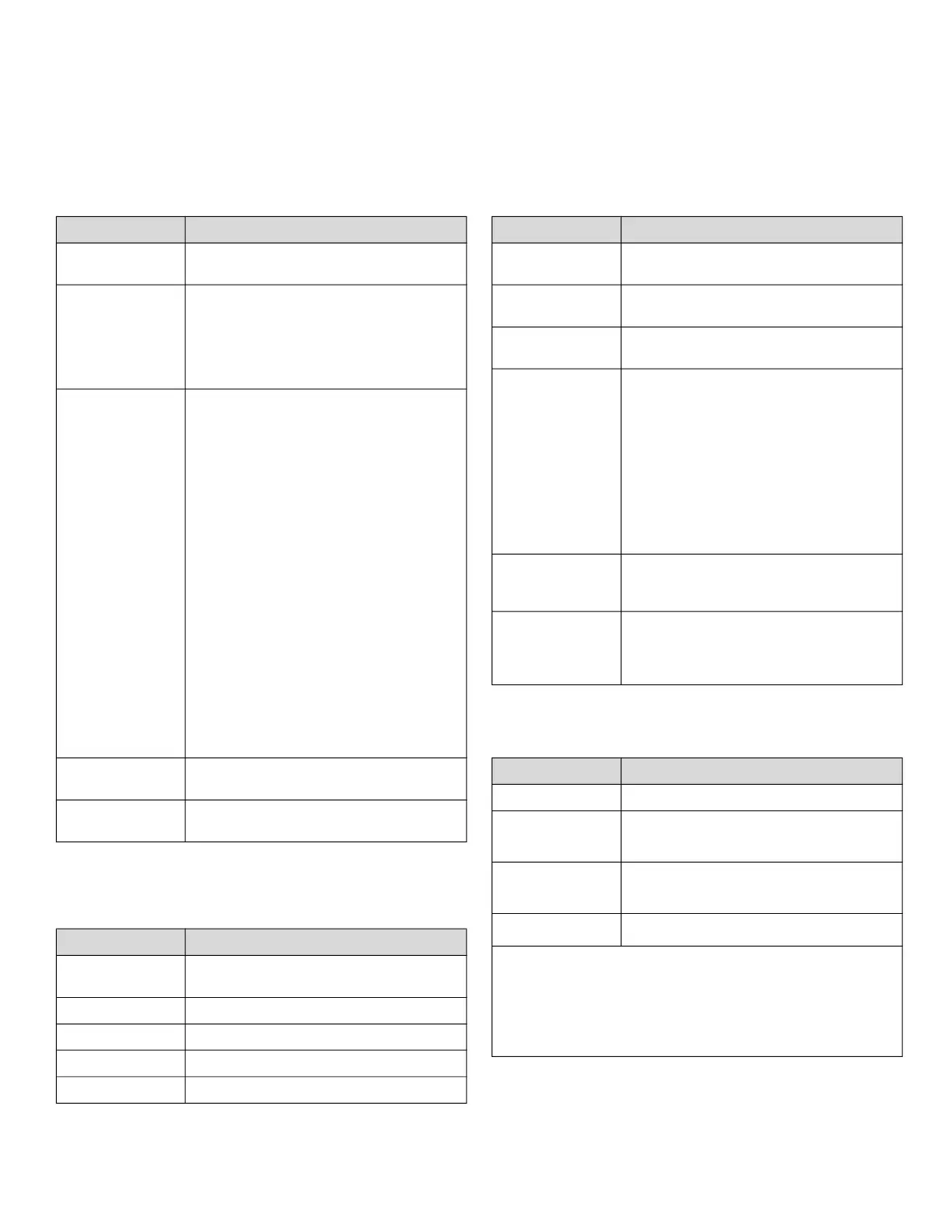
SPECIFICATIONS
Electrical
Operational Environment
Hardware
Integrated Actuator
Table 3 Electrical Specification
Parameter Specification
Rated input
voltage
20 - 30 VAC; Class 2 transformer
Nominal Power
Consumption
IP model: 8 VA; controller and
actuator load (nothing connected to
IO and COM)
MSTP model: 6 VA; controller and
actuator load (nothing connected to
IO and COM)
Full Load
Power
Consumption
IP model: 30 VA; maximum load
including external loads, Sylk™,
communication, BLE, universal IO,
and 20 VDC output (excluding the
load on the solid state relays).
MSTP model: 22 VA; maximum load
including external loads, Sylk™,
communication, BLE, universal IO
output, and 20 VDC output
(excluding the load on the solid state
relays).
If the solid state relays are used, user
needs to determine the full load
power consumption (or VA rating) as
per the below example.
Example for a transformer load (VA);
if there is an addition of parallel load
from two solid state relays with 24
VAC @ 1.5 A: Total transformer load
on a fully loaded controller will be 30
VA + 72 VA = 102 VA.
Frequency
Range
50 to 60 Hz
Auxiliary
Output
20 VDC @ 75 mA
Table 4 Operational Environment
Parameter Specification
Storage
Temperature
-40 °F to 150 °F (-40 °C to 66 °C)
Operation 32 °F to 122 °F (0 °C to 50 °C)
Humidity 5 % to 95 % RH, non-condensing
Protection IP20, NEMA -1
Pollution Level 2
Table 5 Hardware Specification
Parameter Specification
CPU
Crossover processor NXP I.MRT,
Cortex M7
Memory
Capacity
16 MB QSPI Flash, 16 MB SDRAM
Ethernet
(IP Model only)
Two each RJ-45 Ethernet ports.
Real Time
Clock
• 24-hour backup after power
failure.
• In case of power failure, the
controller includes a super
capacitor to retain the time set
with the built-in real time clock
for 24 hours. After 24 hours, the
time will reset to the factory
default time until the user
performs a BACnet Time Sync.
Small LED
Transmission or reception of BACnet
and Modbus communication signal
(green)
Large LED
Controller status such as normal
operation, firmware download,
broken sensor, e.g. green, yellow or
red
Table 6 Integrated Actuator Specification
Parameter Specification
Torque 44 in-lbs (5 Nm)
Run Time
• Floating 108 s at 50 Hz
• Floating 90 s at 60 Hz
Mounting
Shaft
• Round 5/16 – 5/8 in (8 - 16 mm)
• Square 1/4 – 1/2 in (6 -13 mm)
Shaft Length
≥ 1 5/8 in (41 mm)
Position feedback via integrated potentiometer
• Periodic synchronization not required.
• Additional diagnostic, for example, the command to
change the actuator position does not provide a
corresponding sensor reading if the actuator is
stuck or the potentiometer is damaged.

 Loading...


