SPYDER MODEL 7 VAV CONTROLLER INSTALLATION INSTRUCTIONS
31-00475-01 10
NOTE:
Mount the actuator flush with damper housing or
add a spacer between the actuator mounting sur-
face and damper box housing.
Fig. 8 Mounting Controller to VAV Box Damper
Housing when Actuator is not Parallel to VAV Box
Damper Housing
2. Determine the damper ‘full opening angle’ (45, 60,
or 90 degrees). In Fig. 7 on page 7, the damper is
open to its fully open position of 90 degrees.
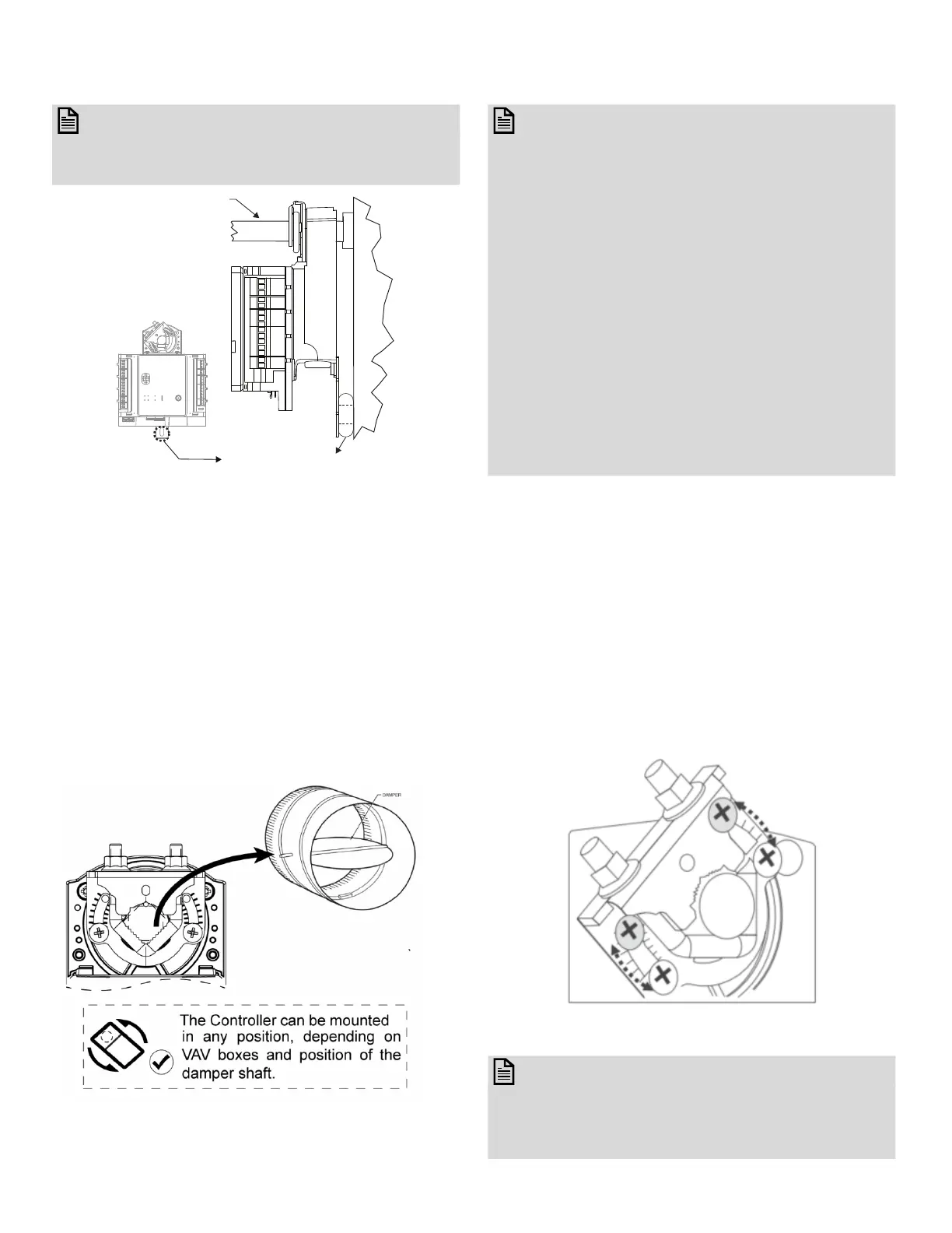
Mounting Actuator onto Damper
Shaft
The Spyder Model 7 VAV controllers can be mounted in
any orientation. Mount them in a position that allows
access to the service button and clearance for wiring,
servicing, and removing BACnet wiring.
Fig. 9 Mounting Actuator on Damper Shaft
NOTE:
The controller is not position sensitive and can be
mounted sideways or upside down. Use the drill-
ing template provided in the box.
The Spyder Model 7 VAV controller's integral actu-
ator does not float inside the housing therefore it
should be installed with a floating mount to allow
for non-concentric travel, which can occur with
damper shafts that are out-of-round and / or
have asymmetrical damper shaft mounts.
If the actuator does not allow any wobble, it is
likely to bind. To prevent this, when installing the
Spyder Model 7 VAV controllers, install it over the
damper shaft and then slide the anti-rotation
bracket underneath and into the mounting slot
but not at the very end of the slot.
Screw the anti-rotation bracket using screws on
the controller.
Tools Required
• Phillips #2 screwdriver for end-limit set screw
adjustment
• 8 mm wrench for centering clamp
The actuator mounts directly onto the VAV box damper
shaft and has up to 44 in-lb. (5 Nm) torque, 90-degree
stroke, and 108 second timing at 50 Hz and 90 second
timing at 60 Hz.
The actuator is shipped with two mechanical end limit
set screws to control the amount of rotation from 12 ° to
95 °. These set screws must be securely fastened in
place. To ensure tight closing of the damper, the shaft
adapter has a total rotation stroke of 95 °.
Fig. 10 Setting the Mechanical End Limits
NOTE:
The actuator is shipped with the mechanical end-
limit set screws set to 95 ° of rotation.
Adjust the two set screws closer together to
reduce the rotation travel. Each “hash mark” indi-
VAV BOX
DAMPER
VAV BOX
DAMPER
HOUSING
SHAFT
ADD WASHER OR SPACER (OBTAINED
LOCALLY) BETWEEN VAV BOX DAMPER
HOUSING AND THE ACTUATOR TAB TO
KEEP THEM PARALLEL.

 Loading...


