SPYDER MODEL 7 VAV CONTROLLER INSTALLATION INSTRUCTIONS
7 31-00475-01
Universal IO Solid State Relay (SSR)
Wireless Connectivity
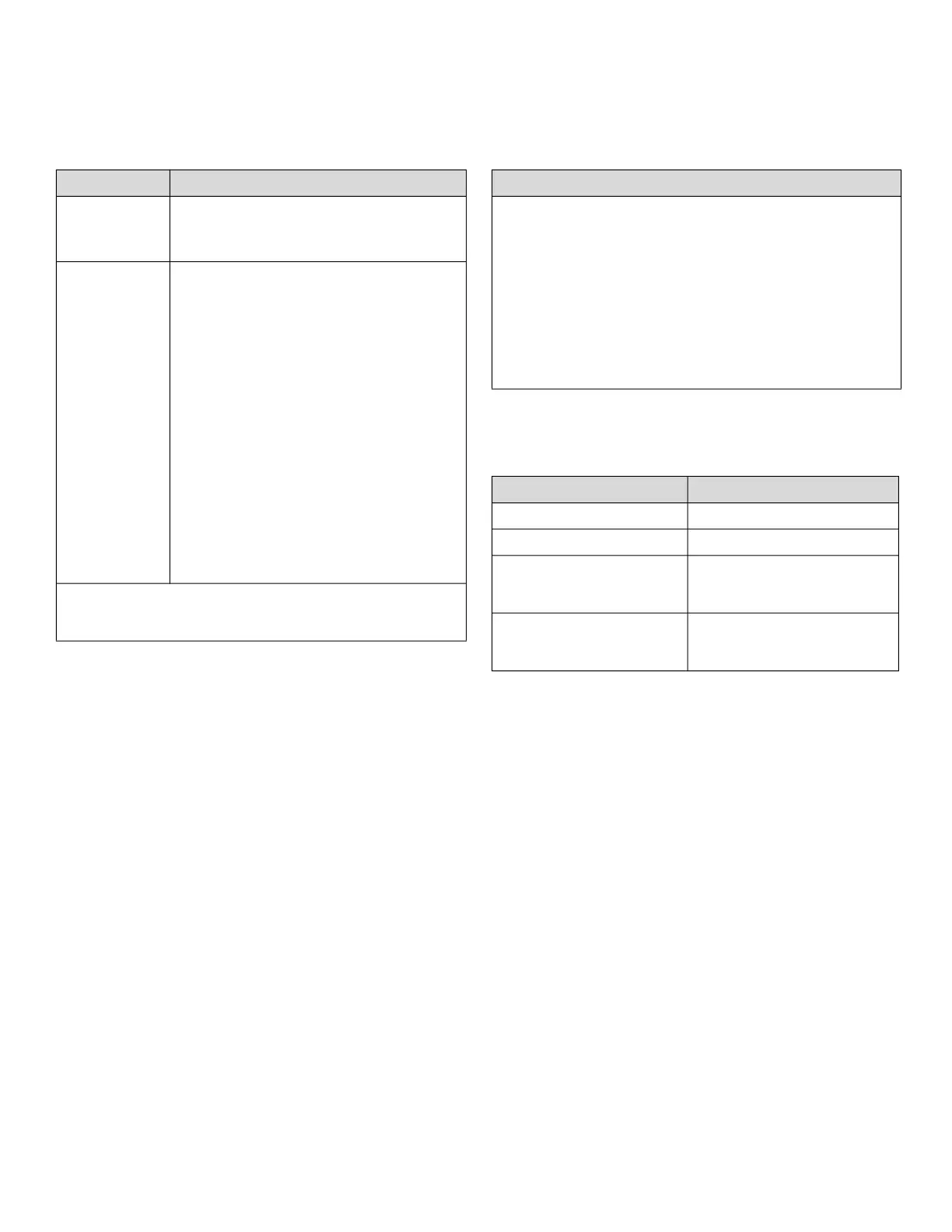
Table 12 Universal IO Specification
Parameter Specification
AO
(Analog
output)
Voltage: 0(2) to 10 VDC direct or
reverse with -3 mA to 20 mA
Current: 0(4) to 20 mA
UI
(Universal
input)
Voltage input: 0(2) to 10 VDC direct or
reverse.
Current input: 0(4) to 20 mA
Sensors: 10k NTC TYPE II, NTC10K3,
10K3A1, 20k NTC, PT100, PT1000,
NI1000 TK5000, Nickel Class B DIN
43760, PT3000, 100 Ohm to 100k
Ohm resistive (custom characteristic).
Hardwired wall sensors: Set point, fan
speed, occupancy override.
Dry contact binary input with direct or
reverse voltage.
All UI can be used for pulse input.
Maximum frequency 100 Hz, Minimum
duty cycle (50 % / 50 %) 5 ms ON / 5
ms OFF.
The Spyder Model 7 VAV controller has a single
common terminal for every two UIOs, which protects
them against 24 VAC mis-wiring and short circuits.
Table 13 Solid State Relay (SSR)
Specification
Solid state relay switches supply voltage and works
with 24 ± 20% VAC and 41 VDC. VDC switching does
not support synchronous motor.
• 1.5 A constant; 3.5 A inrush for 0.1 sec. per SSR
output
• Optional jumper between 24 VAC supply and SSR
input shared by all SSRs.
• All SSR on the controller must be the same: either all
high side switching or all low side switching.
• Keep the jumper in place for high-side switching.
• Remove the jumper for low side switching.
Table 14 Connectivity Frequency Range
Parameter Specification
Connectivity Bluetooth
Frequency range 2400 MHz - 2483.5 MHz
E.I.R.P for CE
(Effective Isotropic
Radiated Power)
20 mW
E.I.R.P for FCC/IC
(Effective Isotropic
Radiated Power)
20 mW

 Loading...


